The Folgertech FT-5 Large Scale 3D Printer Kit
/Folgertech.com recently came out with a new kit for a large scale 3D printer boasting a huge 12inx12in15.75in print area. After getting my feet wet with one of their cheap Prusa i3 Kits, I started to get the itch to upgrade to a more higher end style printer. The cost of this kit was $499 and it took me right around 14 hours to build. The Folgertech 3D Printer Facebook Group was extremely helpful and I'll summarize the additional information I've learned from them in this write up.

General Build Tips
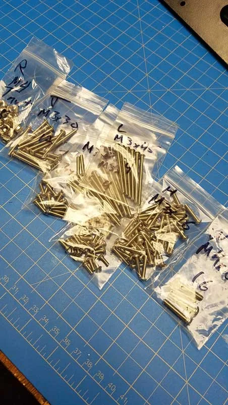
- Sort all hardware into small plastic bags and label them accordingly.
- This serves two purposes. First, you conduct an inventory of all parts. If you find you are missing something, you can contact Folgertech right away to request replacements instead of finding something missing in the middle of the build. Secondly it provides quick access to each type of part. There are numerous nut/bolt sizes and being able to quickly look at the label for each step saves a ton of time.
- Take it slow
- It can be pretty exciting when you're building a 3D printer. You want to get it done as fast as you can and start printing off all kinds of cool stuff. However, it's very important to take your time during the build process. Rushing through steps will lead to re-work and wasted time.
- Label your wire bundles
- I used a cheap label printer to label each set of cables for the end stops, motors, hotend, fan, and thermistors. This makes wiring and troubleshooting much easier in the event of an issue or repair.
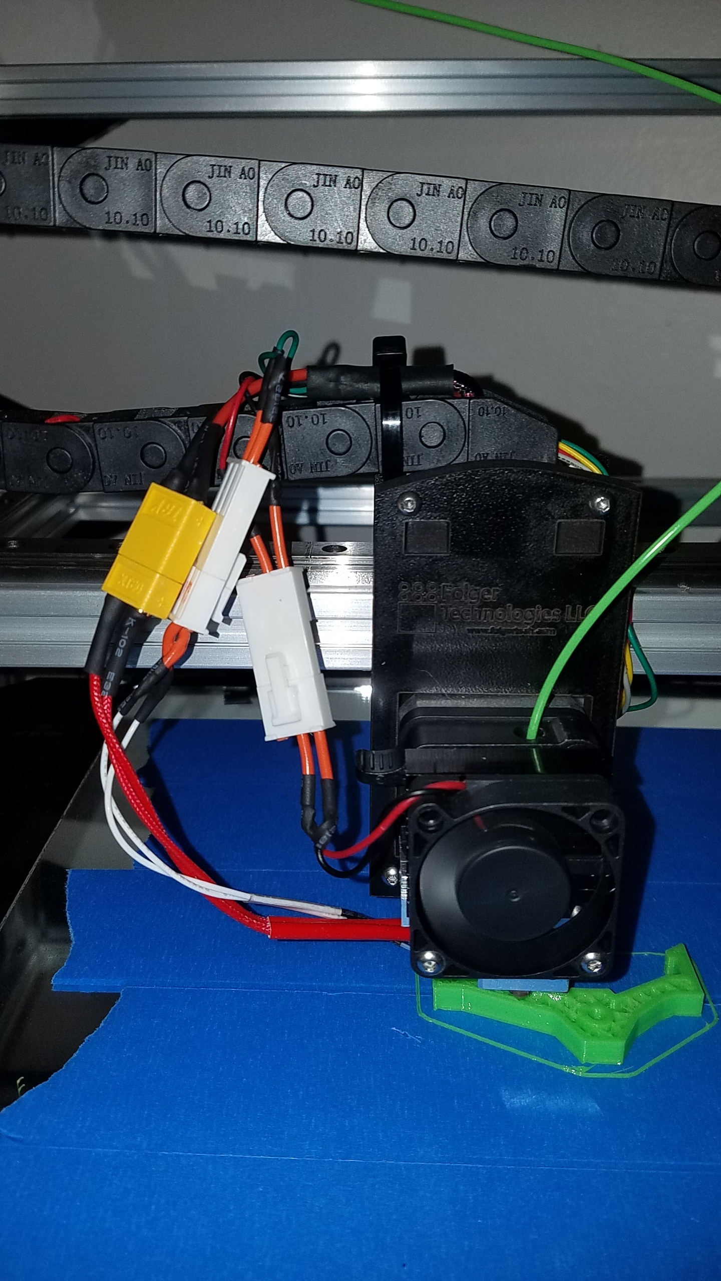
- Replace the stock connectors for the hotend, thermistor, and fan
- I replaced the small, fragile connectors in the kit with some beefier ones. I had some X60 connectors laying around from my quadcopter build and two scrap molex connectors.
- Utilize the great wiring diagram JoAnne K posted at the Folgertech Forums.
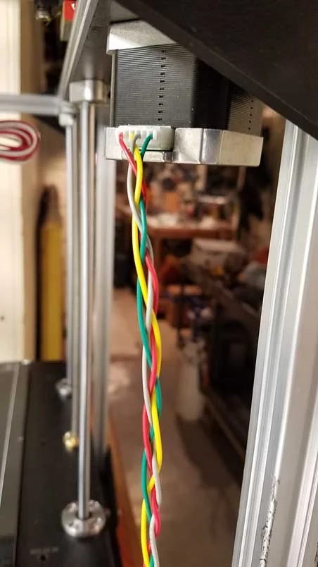
- Be sure to double and triple check the wiring of the Y Axis and Z Axis stepper motors. The Z Axis motor wires need to be wired together with the same colors since they work together, moving in the same direction. The Y Axis motor wires need switched since they move opposite of each other to move the Y Axis.
- Make sure you have all the tools and hardware required before starting
- Similar to my post about the Prusa i3, it doesn't hurt to make sure you have all of the correct tools and hardware before starting. Below is a list of the hardware I used during my FT-5 buildExtra wire - Some of the component wires need lengthened.
- Zip Ties, Heatshrink, Heatgun - Used when extending cables and during wire organization.
- Multimeter - Used to check voltages on Stepper Motor Drivers during initial calibration
- Allen Wrenches - Used for all bolts used in mounting hardware and frame constructions
- Adjustable Wrenches - Used to tighten down bolts of the bed frame
- Dremel Tool - Some of the parts needed a burr or edge grinded down a bit.
- Wire Strippers - A nice set of wire strippers will facilitate wiring
- Calipers - A good set of digital calipers helps significantly when identifying bolt sizes, mounting various components, and aids in calibration.
- Needle Nose Pliers
- Solder/Soldering Iron - The A/C power adapter will require some soldering. Some lead wires also needed lengthened.
- Similar to my post about the Prusa i3, it doesn't hurt to make sure you have all of the correct tools and hardware before starting. Below is a list of the hardware I used during my FT-5 buildExtra wire - Some of the component wires need lengthened.
Problems Encountered During Build
Note: Folgertech is still working on the build document for this printer. Some of the below problems may be corrected in further versions.
- Gantry Spacing
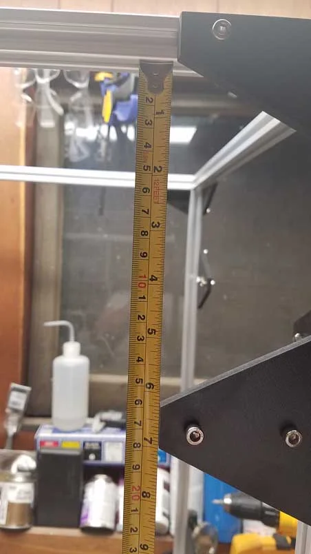
- The instructions mention to use a part of spool holder setup as a spacing guide. To me, and many others, it was quite unclear and we assumed it was the PVC pipe. The pipe is not the correct length, so my frame would have been off if I had used it. Instead, use a tape measure and 160mm as the distance for this step. See the picture below for clarification.
- Various Mentions of Wrong or Missing Screw Sizes
- The instructions have a few wrong screw sizes. The kit comes with plenty of extra hardware so just replace with the next closest size.
- Wires too Short
- There were a couple sets of motor wires and one set of endstop wires that were too short to reach the control board. These were lengthened using some scrap wire and heatshrink to cover the soldered connection.
- Instructions show the electronics fan facing the wrong direction and you can't install it without extra hardware.
- In the instructions, the fan is shown mounted so that it is blowing air out of the case. It should be blowing air over the stepper motor drivers. Without sufficient cooling, the stepper drivers can (and did on my printer) overheat, causing missed steps and stopped stepper motors. When you flip the fan the right way, the top of the fan will hit the enclosure. I needed to use a few washers to space it out.
- Z-Axis Seizing and Would Not Increment.
- The likely-hood that you've constructed this printer to be 100% square and lined up is probably pretty low. When the top and bottom Z-Axis self aligning bearings are both tightened down, it can cause the Z-Axis to fail to increment while printing. To solve this, I loosened the top self aligning bearings to allow for a bit of give as the build plate moves up and down. So far, it has fixed the issue.
- The instructions do not touch upon installing the firmware. When uploading the firmware found on the Folgertech FT-5 Google Drive page, make sure to select the correct COM port and Board in the Arduino Software.
- Arduino Mega or Mega 2560
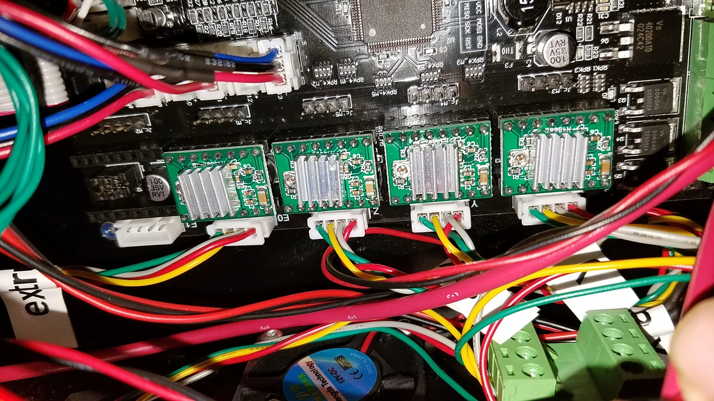
- There is no mention of calibrating your stepper drivers or placing heatsinks on the stepper motor drivers.
- Dustin has a great video on his channel as well as the correct voltage values for the FT-5 printer and the heatsinks are stuck on by peeling off the backing and sticking them on the chips. The photo I have below is wrong, the heatsinks should be rotated 90 Degrees. Also, keep in mind you are trying to tune the stepper drivers so that they have just enough power to move the motors. If you set them too high, like I did originally, the motors will skip and the drivers could overheat, halting any movement.
- The Hotend/nozzle assembly fell out of my extruder assembly during a print.
- I left a print and when I came back the nozzle had fallen out and the print was a mess. To prevent this from happening, heat up the extruder and tighten the set screws. Be careful not to burn yourself!
- Clarification Photos
- I've added a couple photos that help with the build and orientation of components.

Construction and Calibration Tips
- Braid Wires for Neater Wiring
- I braided most of the wires coming from the motors
- Belts and Pulleys
- When looping the belts around the pulleys, I used a zip tie to keep them around the pulley while I fished the belts through the axis components.
- Use some kapton tape to hold the screws in when mounting the LCD panel.
- 100mm Cal
- There are a bunch of guides out there that cover this so I won't explain it fully here. Essentially you mark 100mm worth of filament from the top of the hotend. You then tell the printer to extrude 100mm and make any adjustments to the steps/mm setting in the firmware.
- Z Axis Endstop and Bed Leveling/Glass Plate
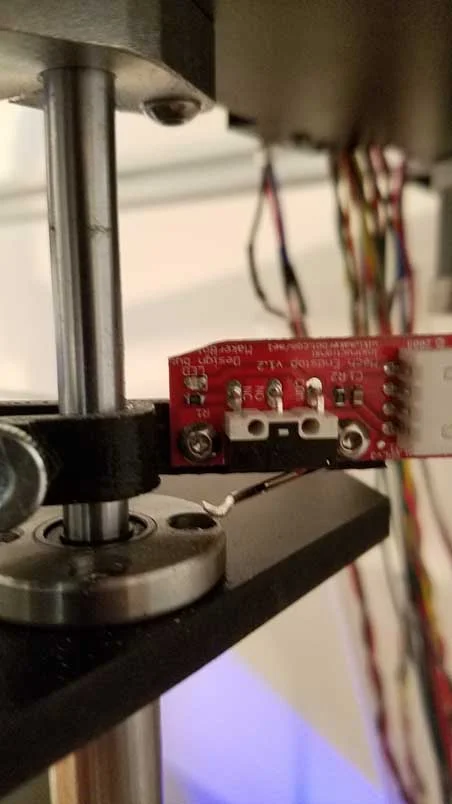
- The supplied Z axis endstop doesn't quite fit. I used a dremel to grind down a corner so the endstep can be mounted high enough for the bed to be leveled correctly. I also ditched the supplied aluminum build plate as it was slightly bent and made leveling a headache. I replace it with a 12x12in mirror tile from home depot. They're cheap, 6 tiles for $10, so if one breaks it's not a big deal. I print primarily PLA and cover my build surface with a layer of Blue Painter's Tape and spritz of hair spray if I'm having trouble with adhesion.
- Sturdy Surface
- You want to make sure your build table is very stable. The printer moves fast, and those fast jerky movements will wiggle an unsturdy table around, affecting your print. I ended up wedging some folded paper sheets between the table and my desk to keep it stationary.
- Use binder clips to guide filament until better solutions can be printed or made

Print Quality
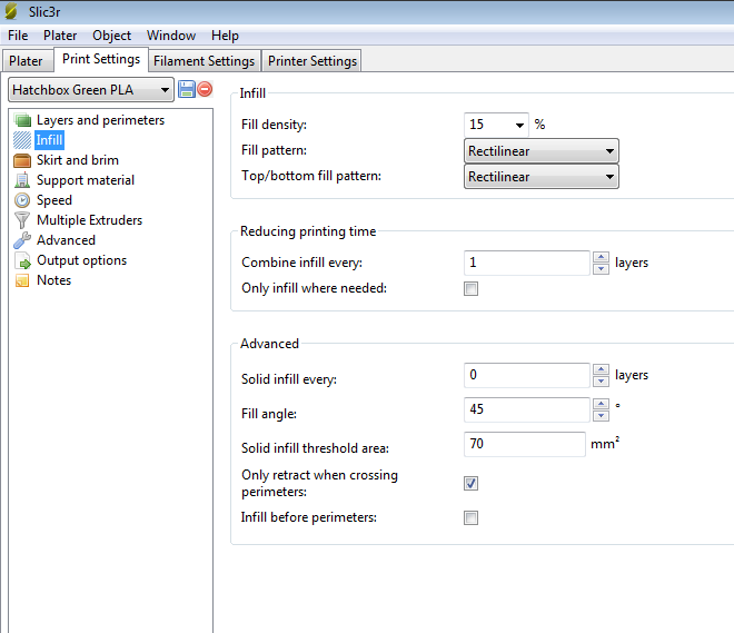
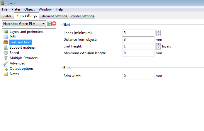
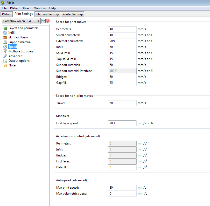
After a few problems with the Z-Axis skipping and overheating stepper drivers, I finally go the printer working nicely. The prints have been coming out very well and I'm very pleased with the quality. Once I fixed my major oversights, leveled the bed, and determined the correct printing temperature for my Hatchbox Filament, the FT-5 printed like a dream. One of the main reasons I was interested in this kit was the speed. My old i3 was reliable but the print speed left a lot to be desired. This FT-5 can go incredibly fast and is very accurate, with printing speeds of 100mm/s. For larger, less intricate parts, this speed can be increased even more. I printed out a calibration benchmark Benchy boat and I was thrilled with the results. It was printed at 0.2mm layer height at 80mm/s. I used a small cooling fan that I just taped to the frame (a more permanent solution in the works). I've also included my Slic3r settings below. I look forward to using this printer to design, create, and have fun!
Let me know if you've built the FT-5 kit and found other issues worth mentioning!

