Quadcopter Part 3 - Soldering Connectors and PDB Layout/Mounting
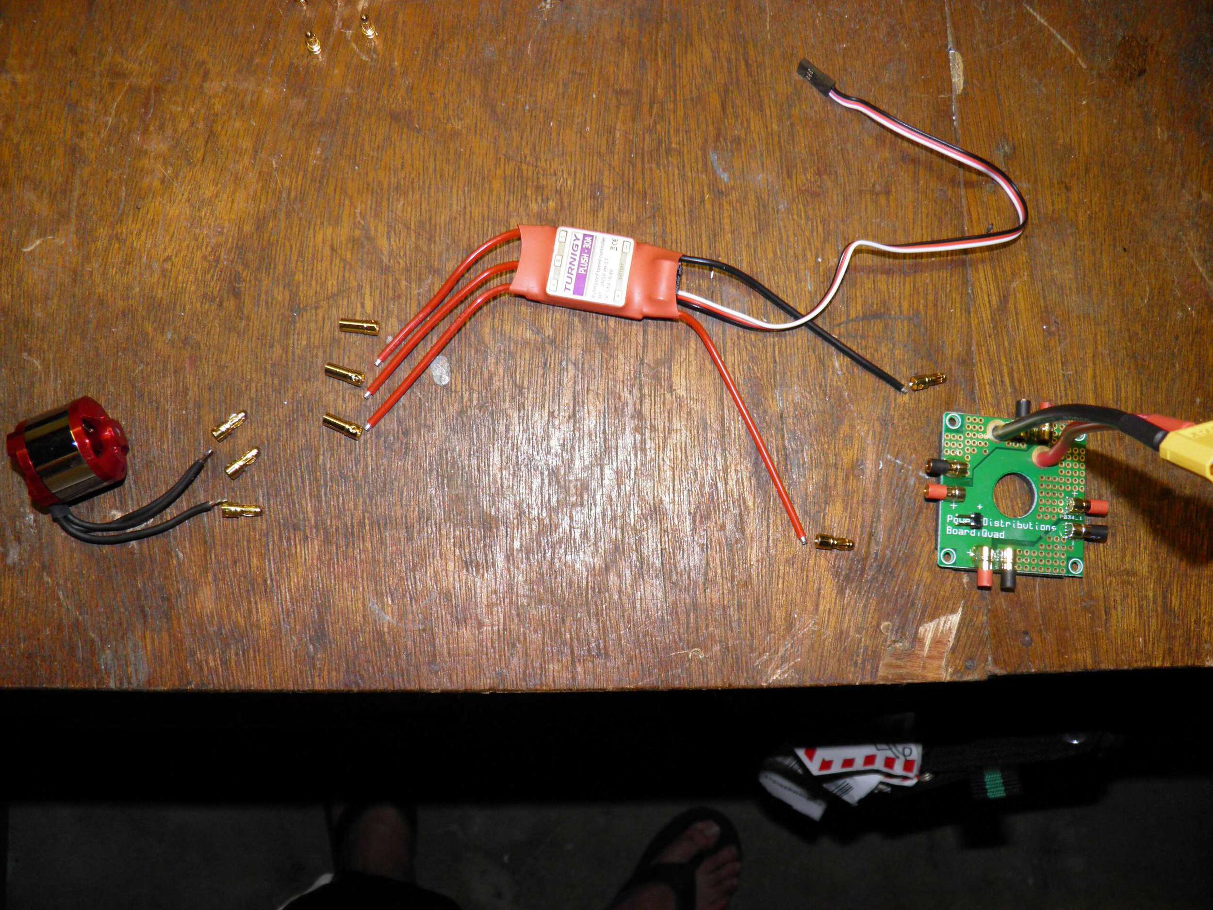
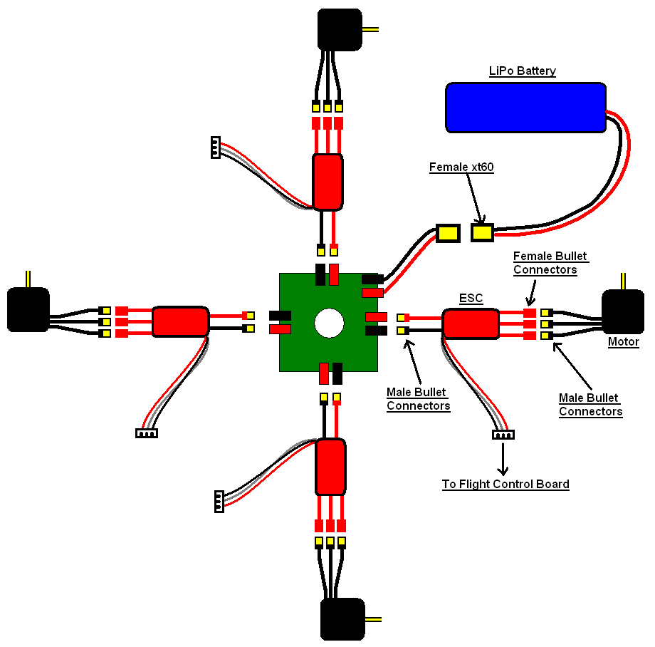
/Once the parts came in (2.5 weeks after ordering) I started with the power supply portion of the quadcopter. The power distribution board, or PDB for short, is supplied by a battery with a xt60 connector and distributes the power to the four ESCs. The ESCs then control what percentage of that voltage gets to the motors which in turn controls the speed. The batteries did not have the xt60 connection so a new connector will be soldered to the battery leads. The ESCs and motors will also need connectors. They will use 3.5mm bullet connectors, which match the PDB. The motors will have three male bullet connectors. The ESCs will have three female bullet connectors on one side and two male bullet connectors on the other side. These will then be connected to the PDB.
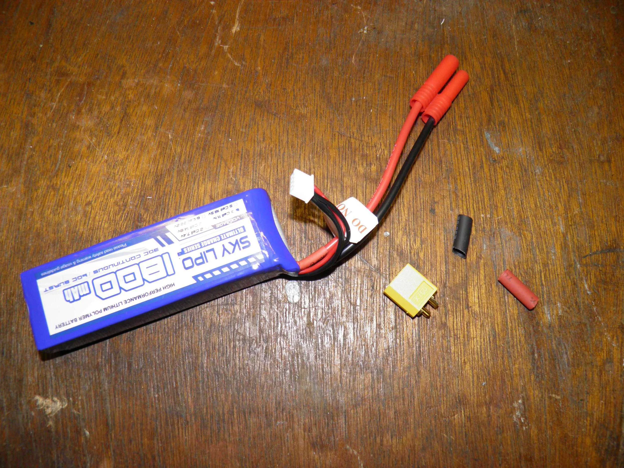
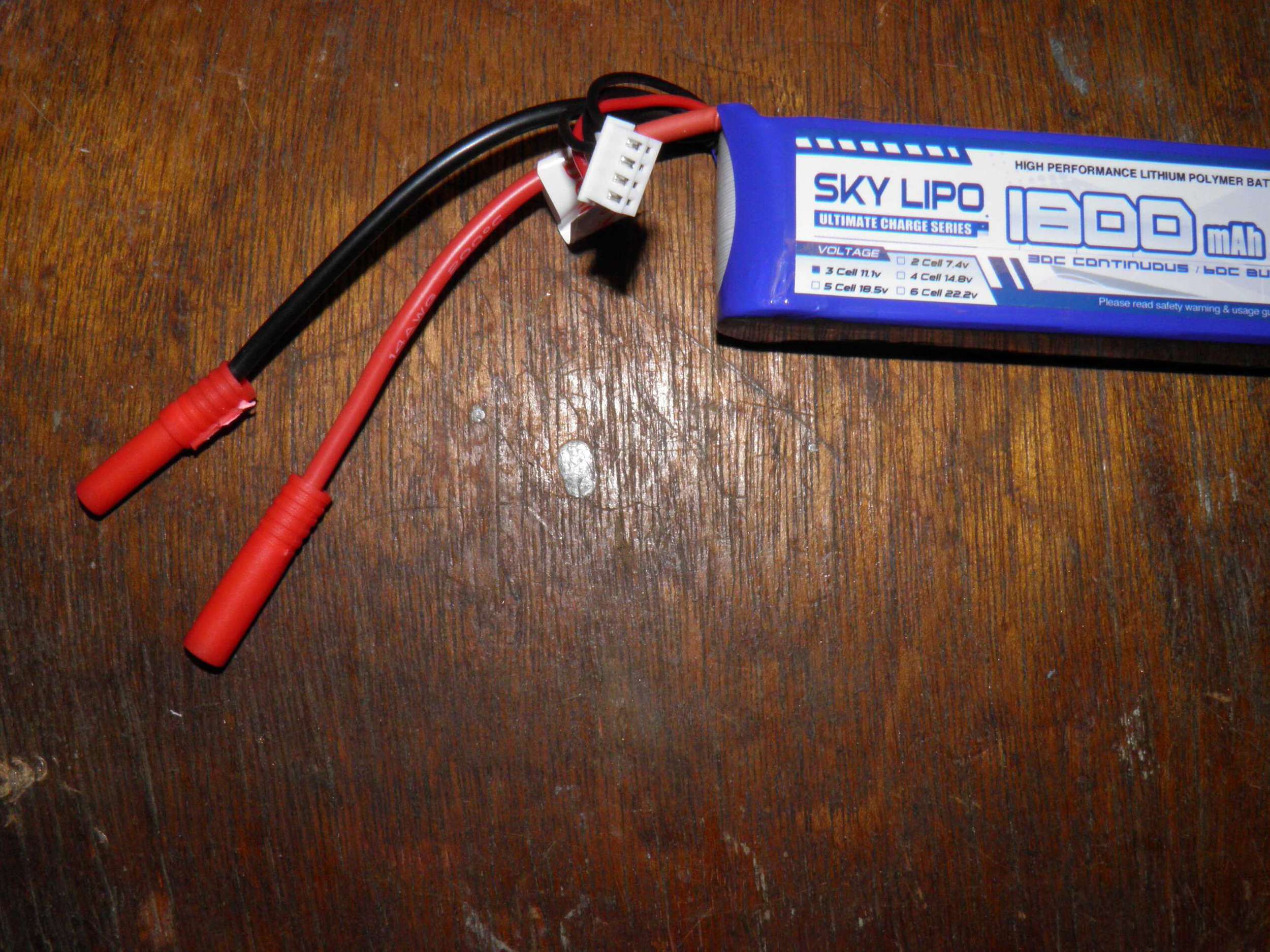
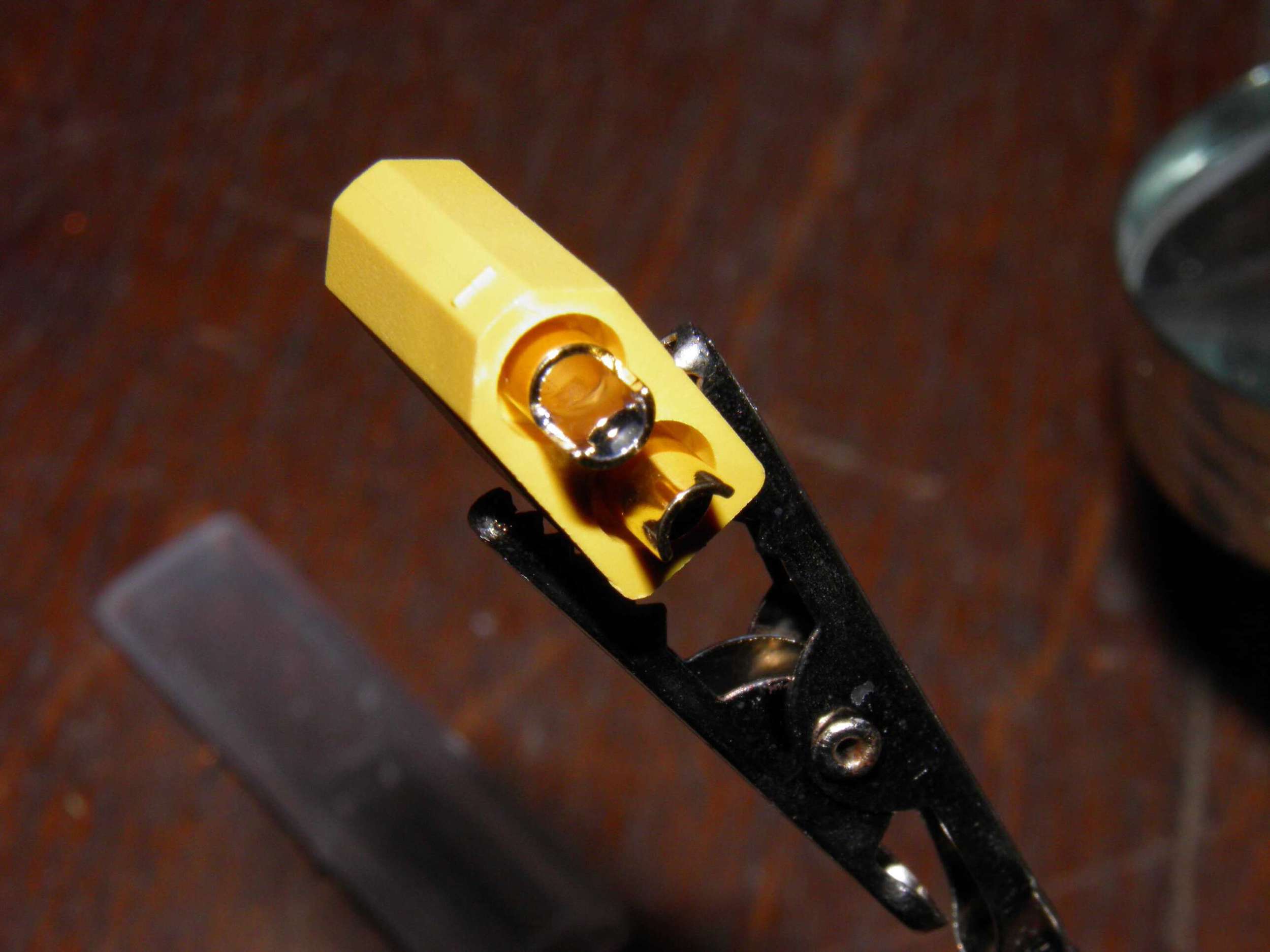
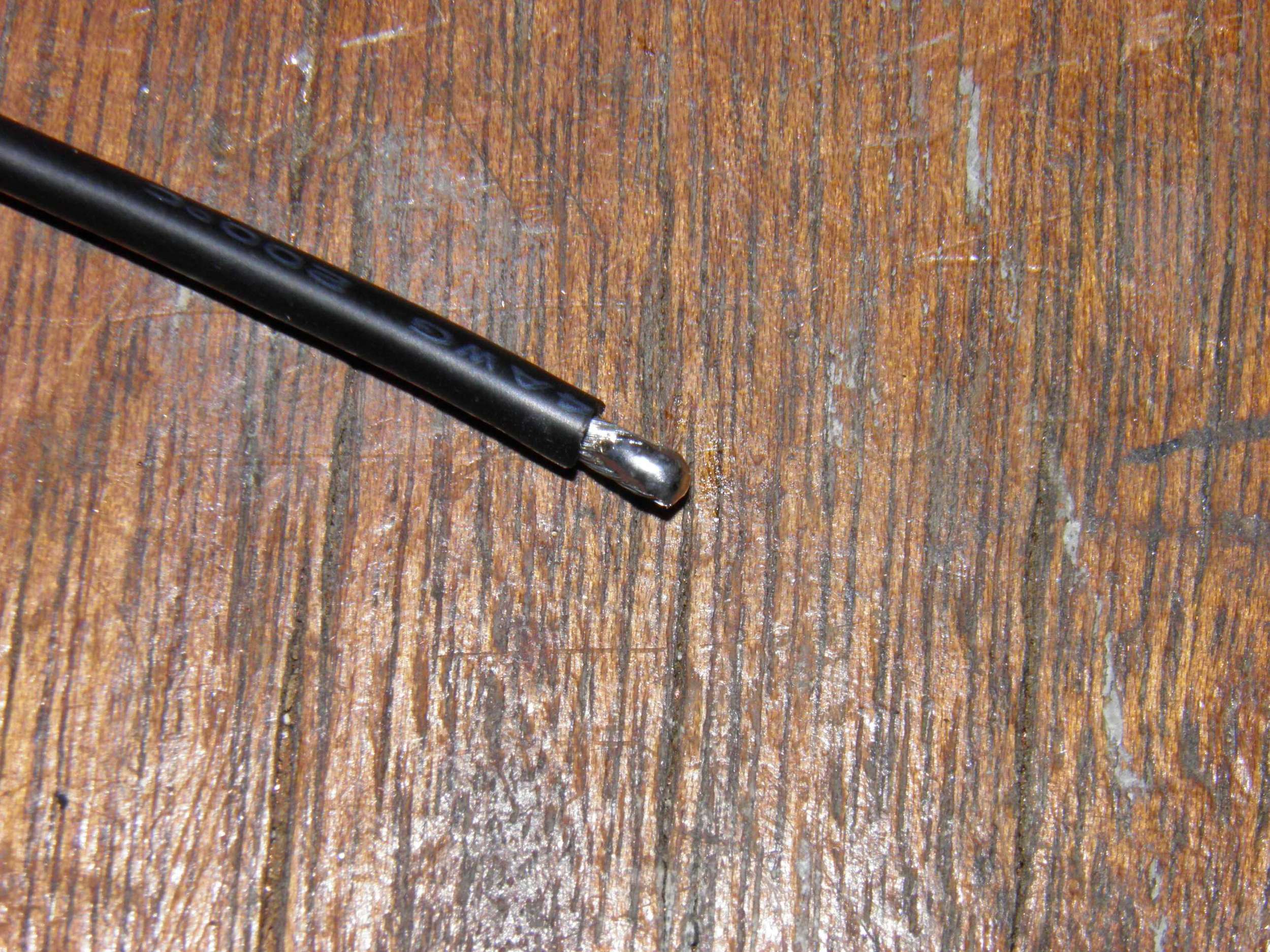
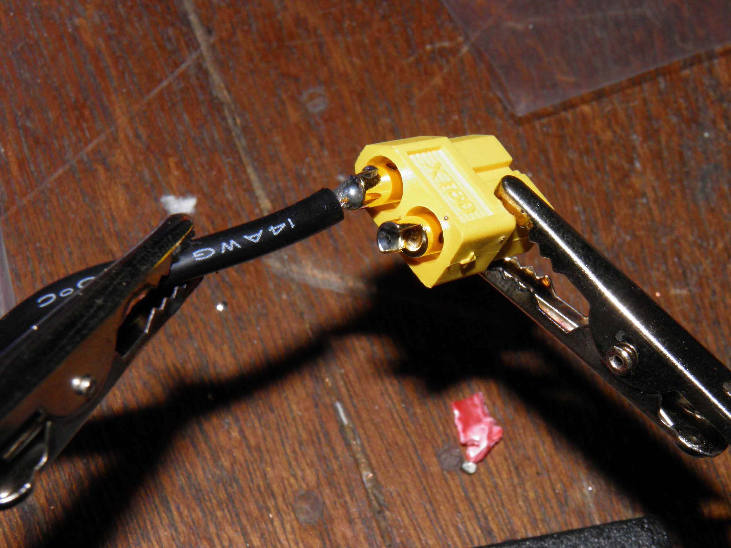
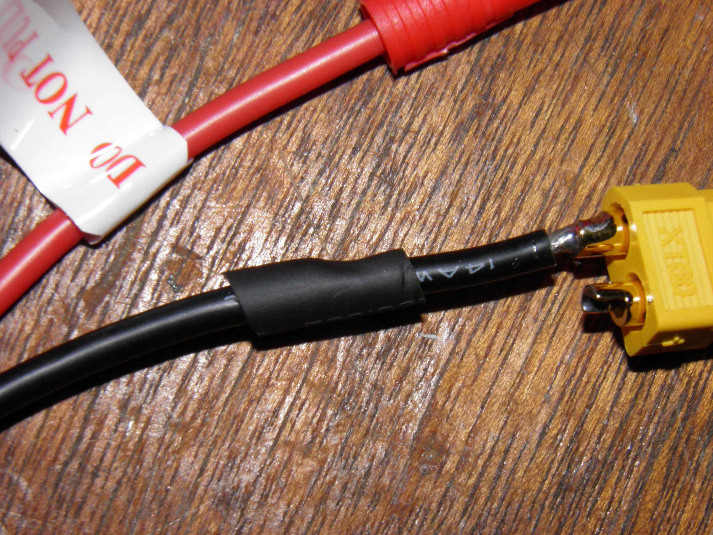
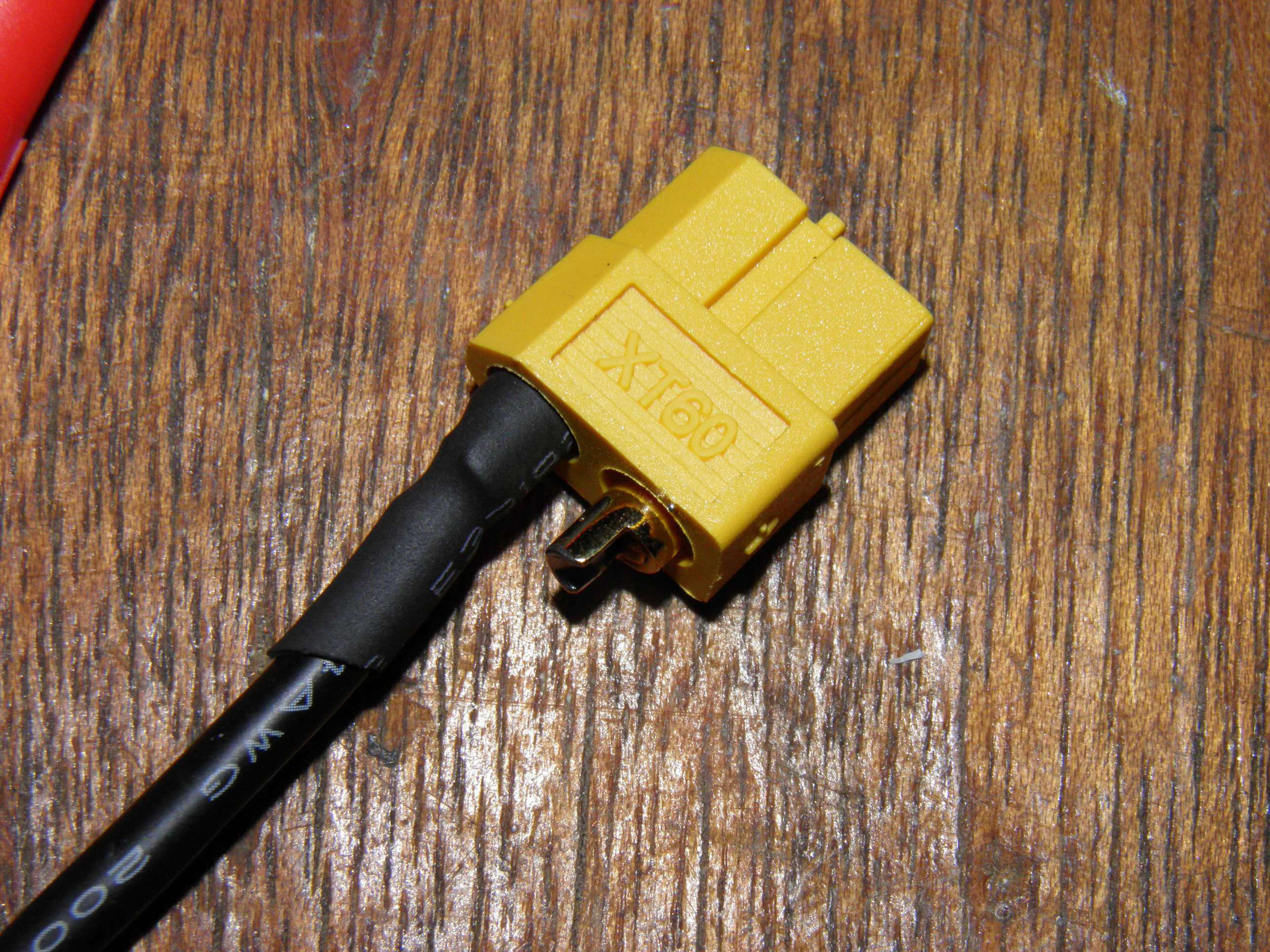
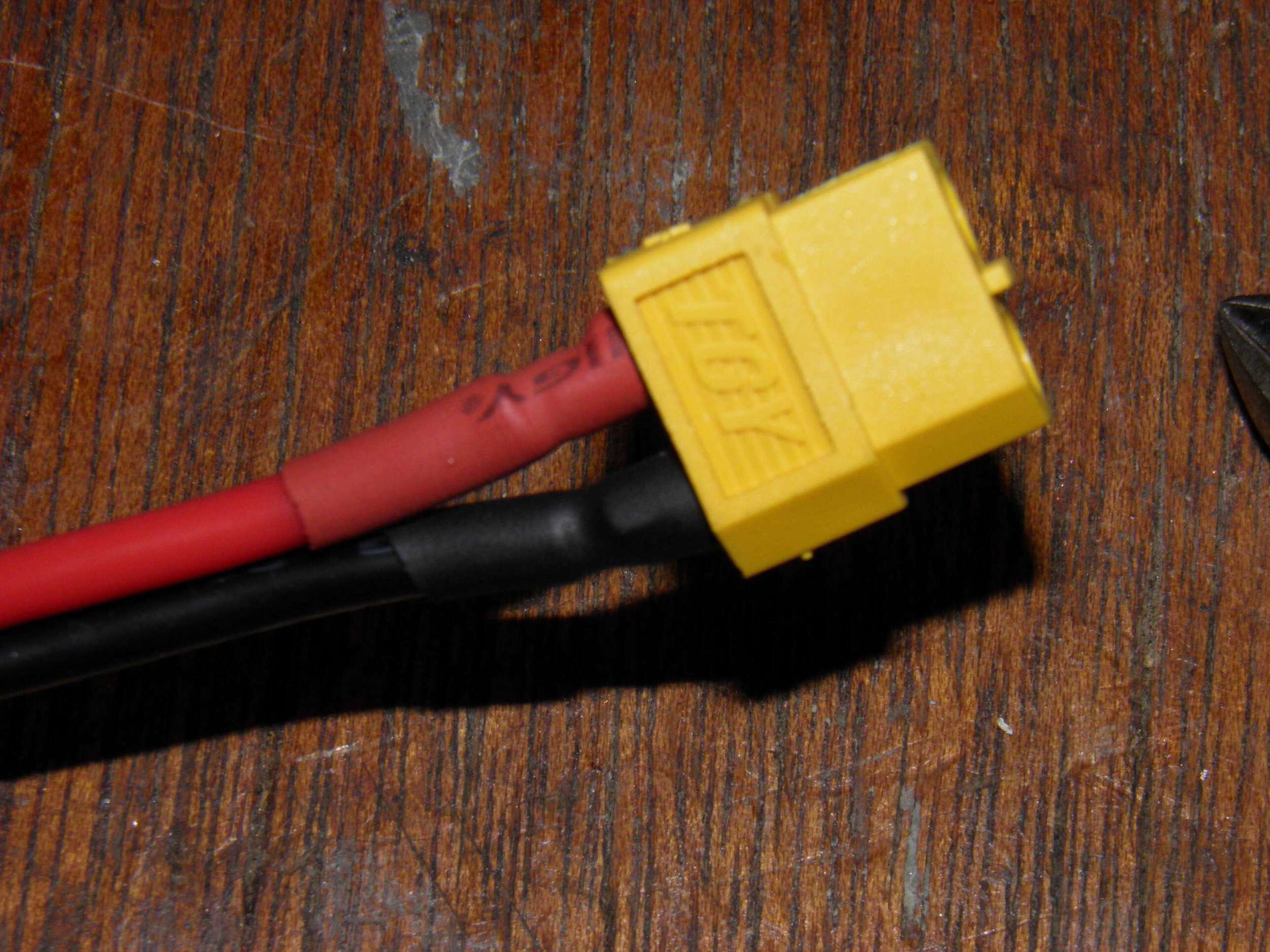
The LiPo batteries I purchased have two connectors on them. The red connector is for the positive and negative voltages and the white connector provides cell level feedback to a charger or LiPo low voltage shut off device. The PDB has a male xt60 connector so a female xt60 connector will be soldered to the batteries. To start, I separated the red connector. Be careful not to accidentally cut and/or short the wires. Shorting a LiPo will damage the battery. Next I put the female xt60 connector in one of my helping hand's alligator clips and tinned the two connections and the two wires to be soldered. Be mindful of the polarity you are soldering to and always double check. I used heat shrink to cover up the exposed metal of the connectors.
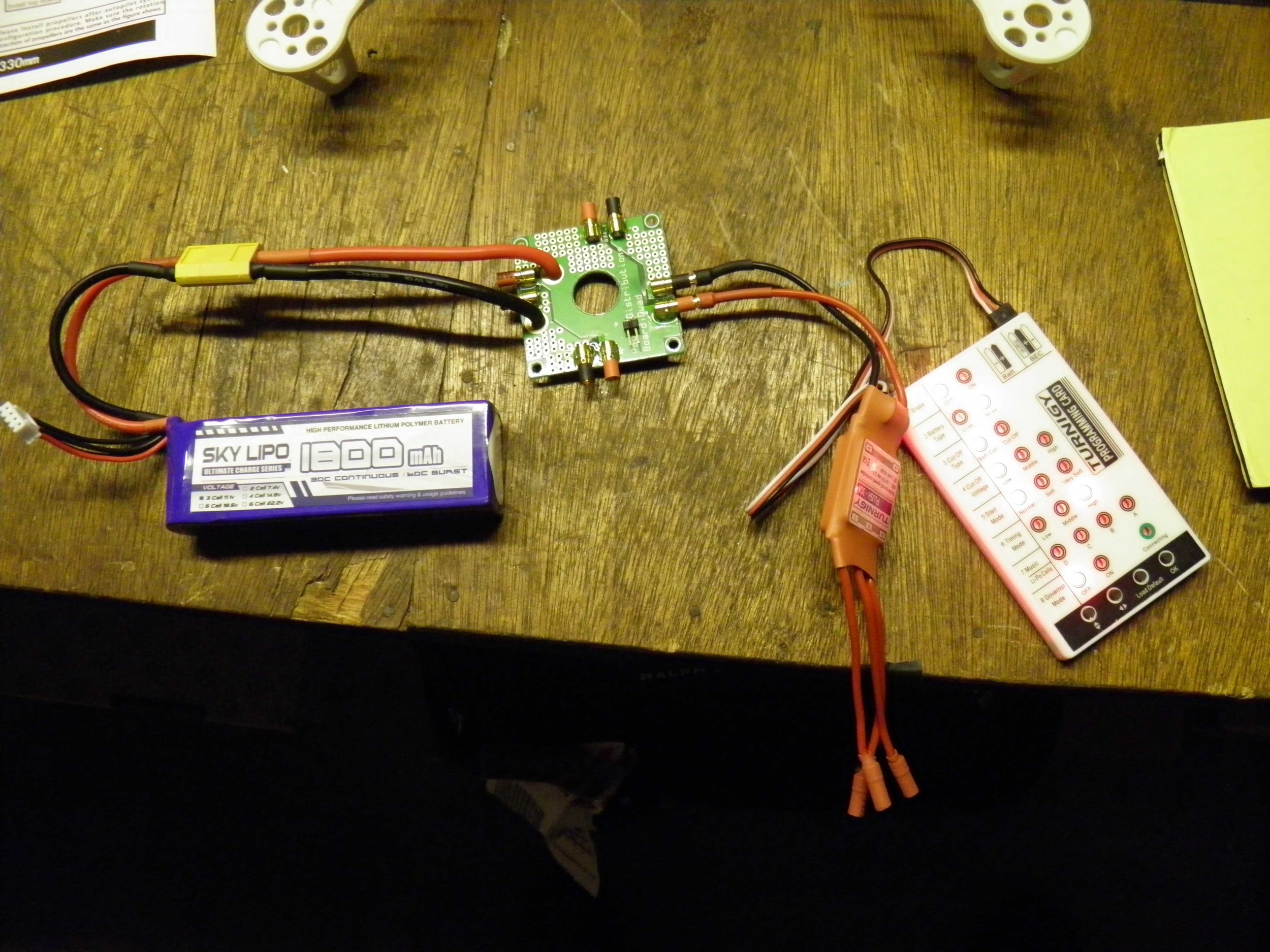
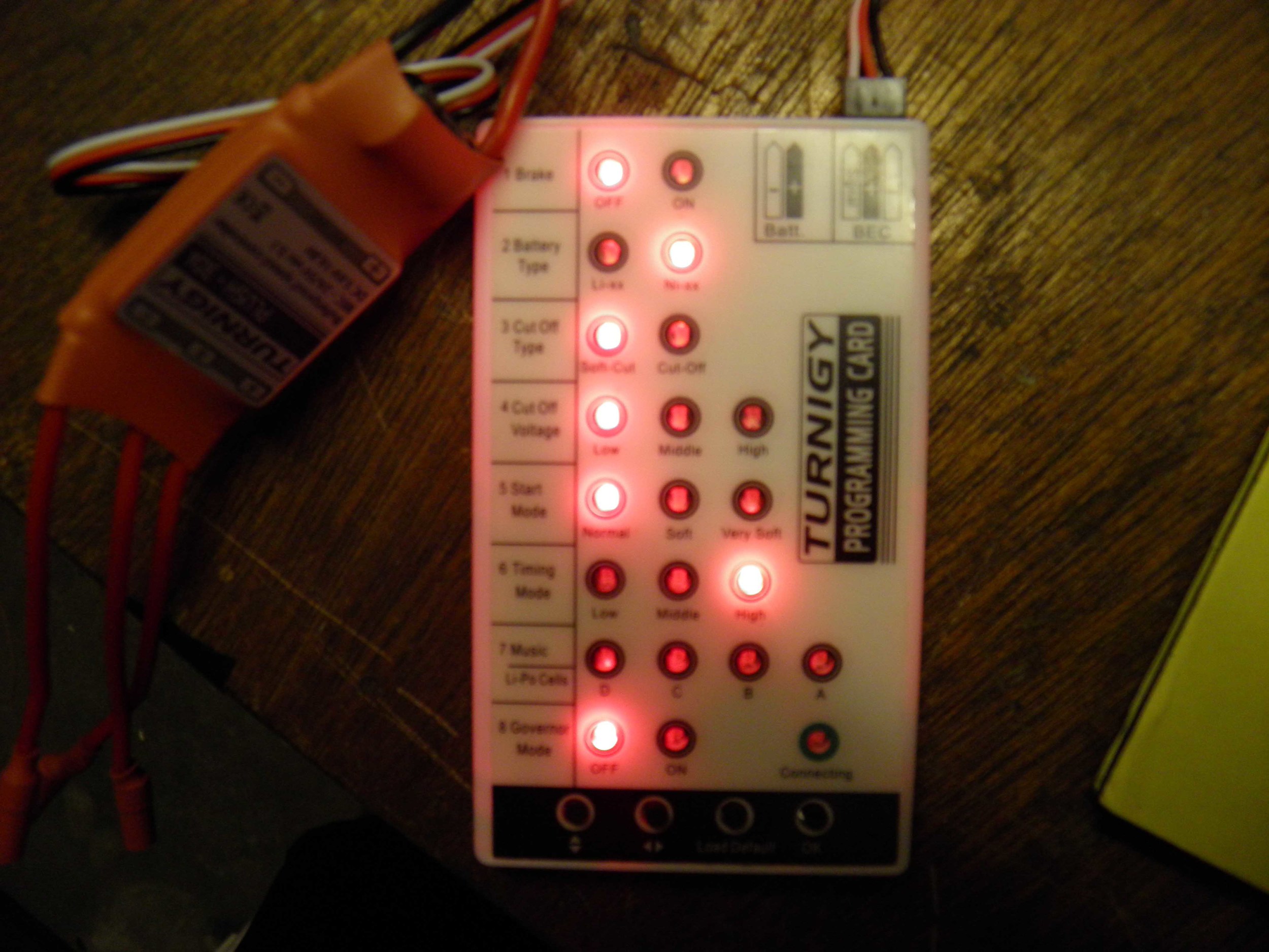
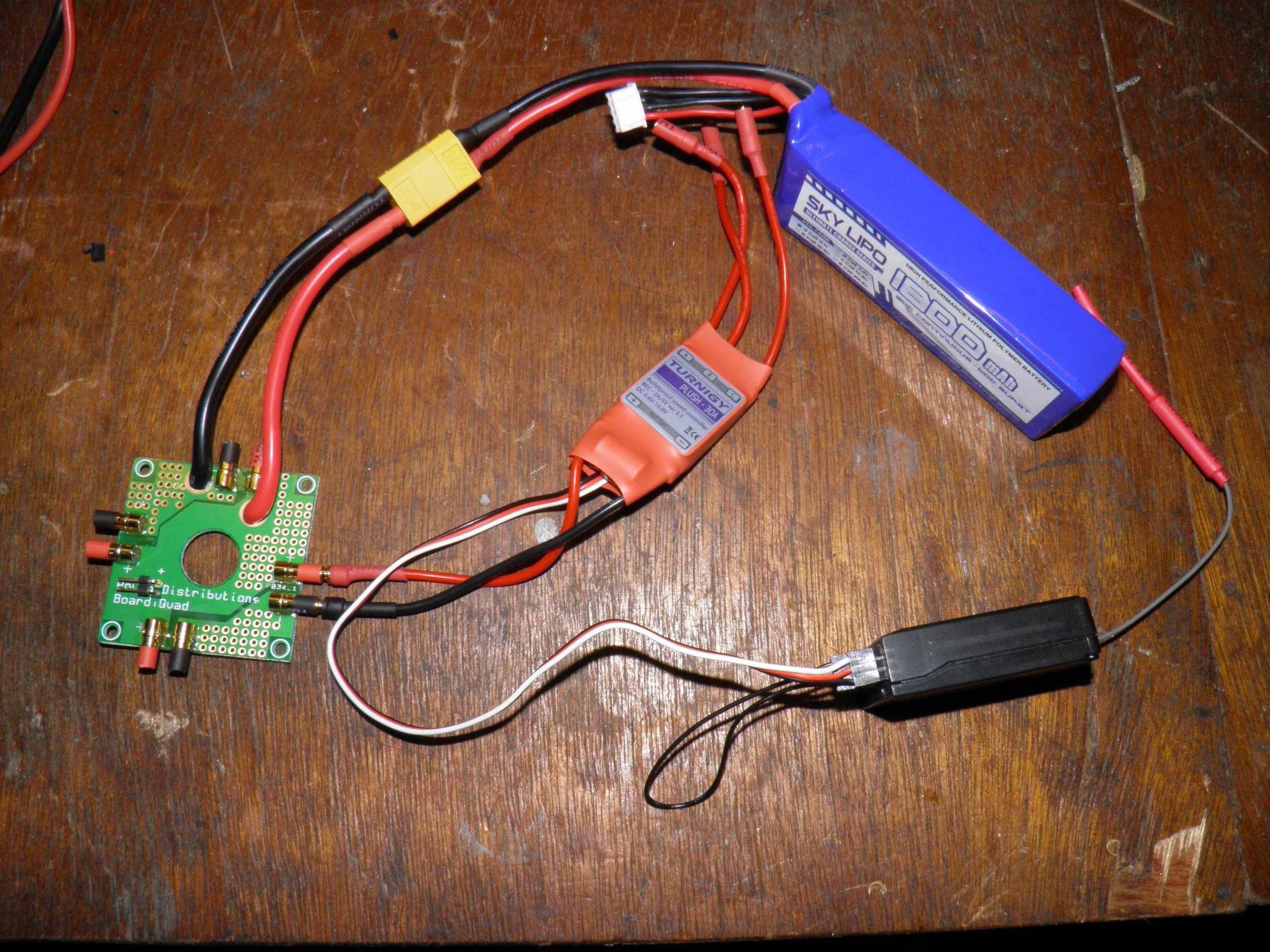
The bullet connectors are a bit more tricky. You definitely need a pair of helping hands for these. I set up a bullet connector in one alligator clip and secured the wire in place with another alligator clip. I then heated up the connection and fed enough solder into the connection until it was fill up and a solid connection was made. Before mounting the ESCs, you will want to program them. Connect the ESC up to the programming card FIRST and then connect it to the battery. Navigate the menu using the programmer's buttons and make the settings match the picture. I've also included a diagram of the connection types and the full power distribution layout.
Programming Card Meanings:
- Brake - OFF - This has to do with the speed controller's motor/throttle interaction. When the throttle is reduced, the ESC will brake the motor. We don't want our ESC's controlling the motors, the flight control board will handle that.
- Battery Type - Ni-xx - If Li-xx is chosen, the ESC will guess the low voltage cutoff. Ni-xx will allow the low-voltage alarm to tell you when to land and prevent the ESCs from cutting power unexpectedly.
- Cut-off Type - Low - This is similar to the battery type. You don't want the ESC deciding when you're going down, you'll use the low voltage cutoff alarm for that.
- Start Mode - Normal - This determines how fast the throttle controls are applied to the motors. Leave this on normal so throttle adjustments are immediately sent to the motors and not delayed.
- Timing - High - High is the preferred setting for quadcopters.
- Music - Leave alone.
- Governor Mode - Off - You don't want the ESC supplying constant speed to the motors on a quadcopter, the flight control board will handle this.
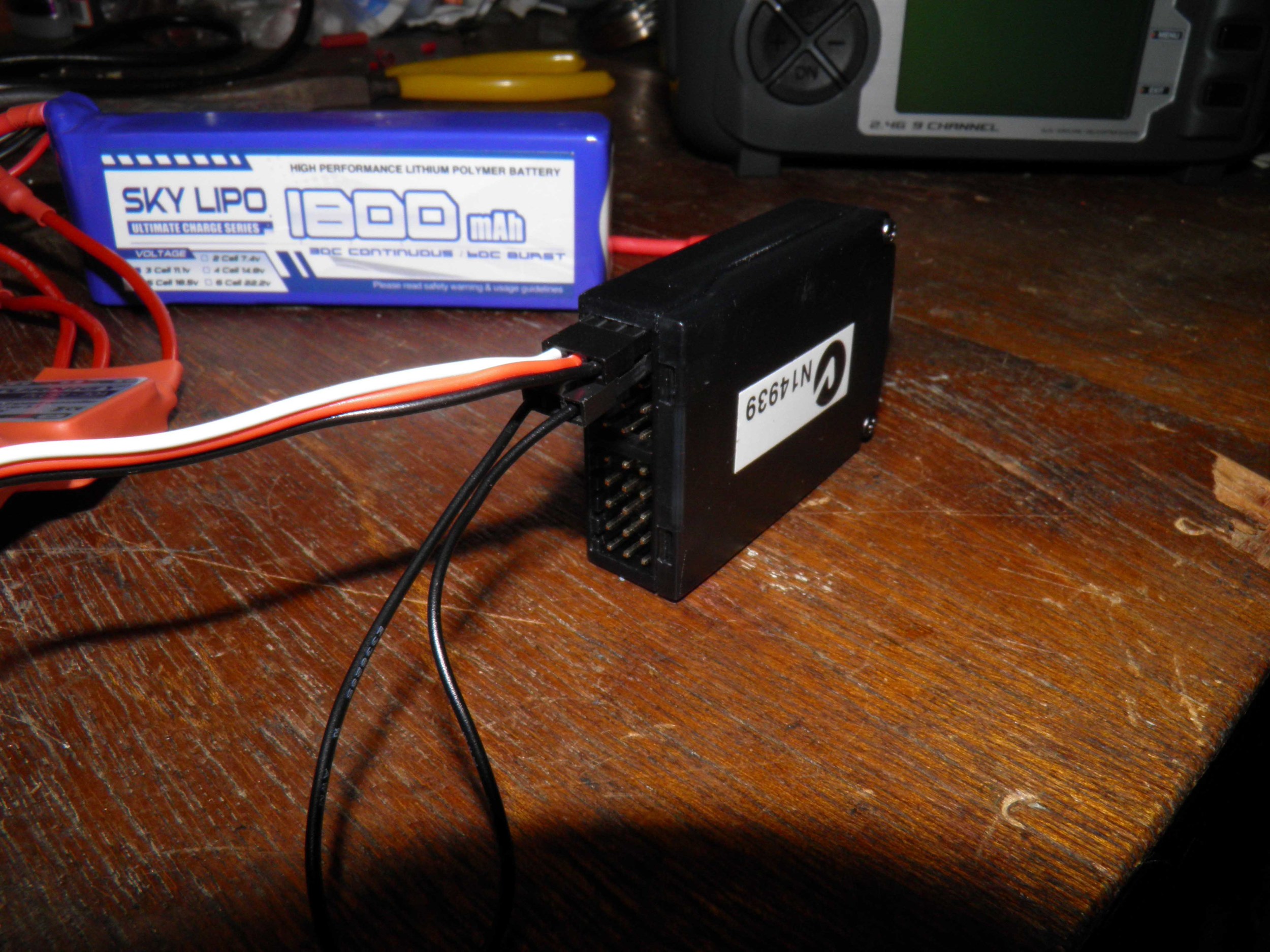
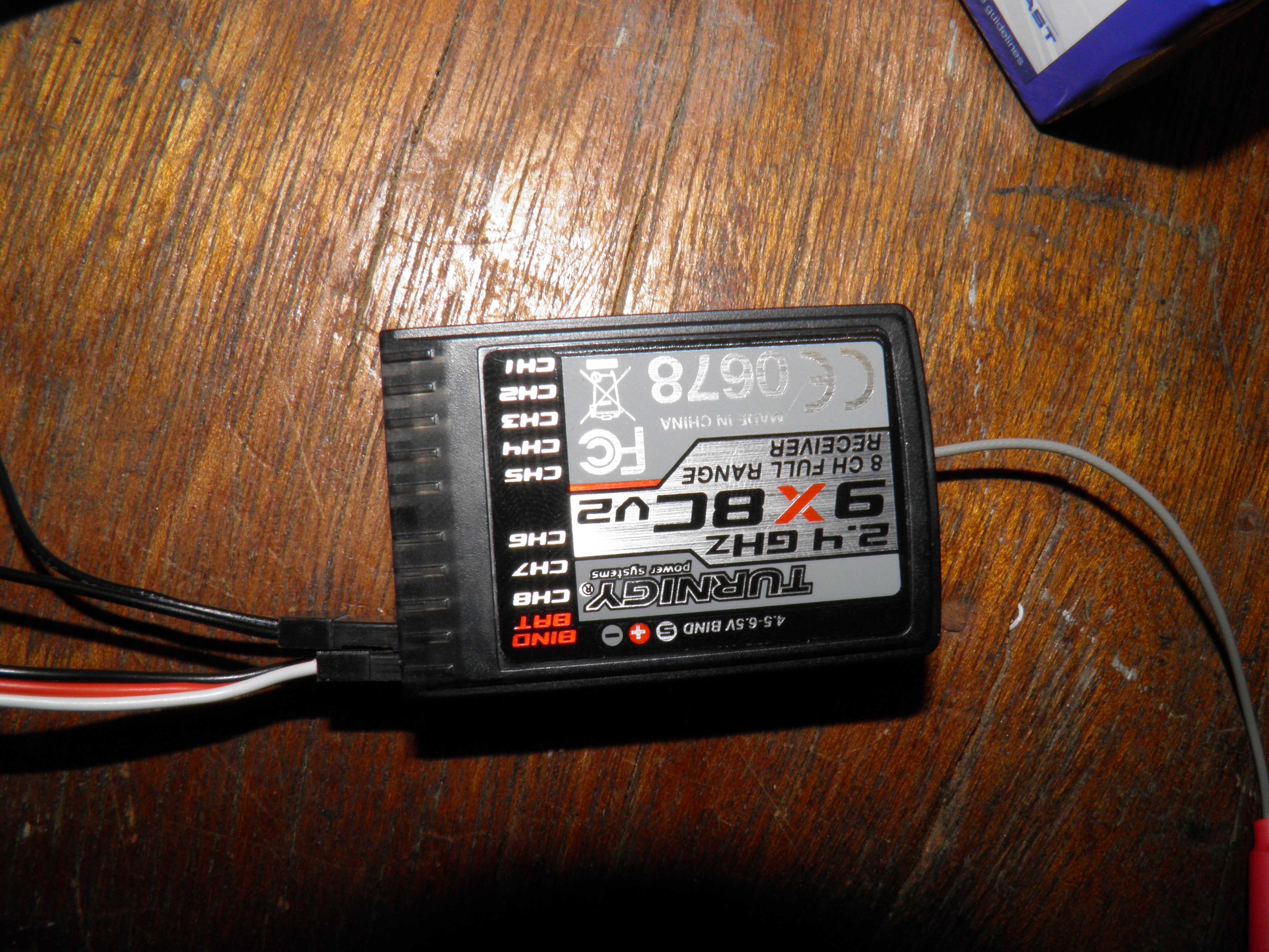
The Rx/Tx can be paired at this time as well. Connect up the battery, ESC, binding jumper, and Rx as shown in the picture. *Note, the terminal sticker on the Rx is backwards, hook it up like the picture. The Rx should have a blinking red light meaning it's ready to pair. Remove the battery from the Rx and begin the binding process. Hold down the bind button on the back of the turnigy 9x and turn it on. While holding the bind button on the Tx down, apply power to the Rx. Unplug the bind plug, and remove the power from the Rx and turn off the transmitter. Re-apply power to the Rx and turn the transmitter on. A solid red light should light up within the Rx signifying the Rx/Tx are connected. There are various youtube tutorials out there for this process if you're having trouble.

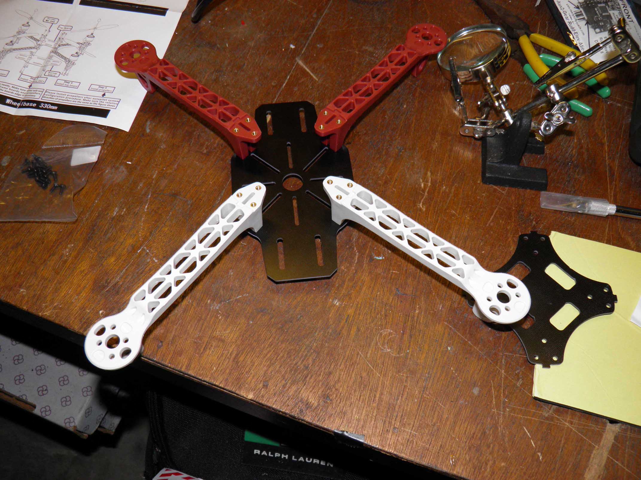
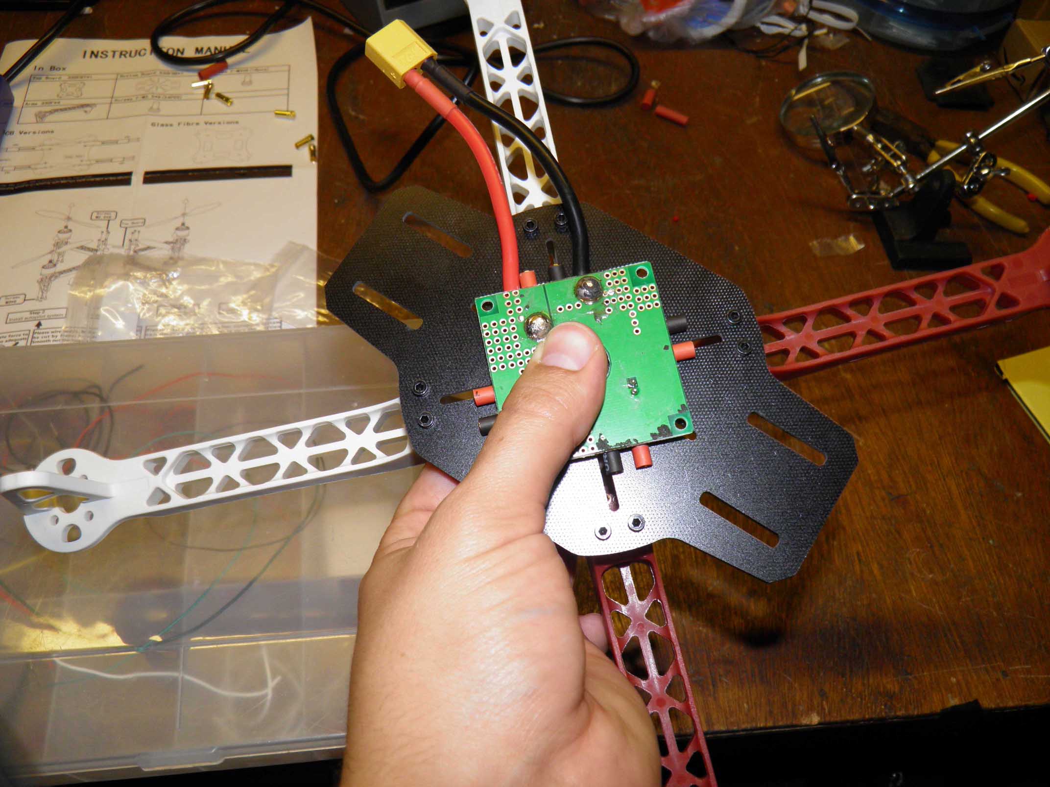
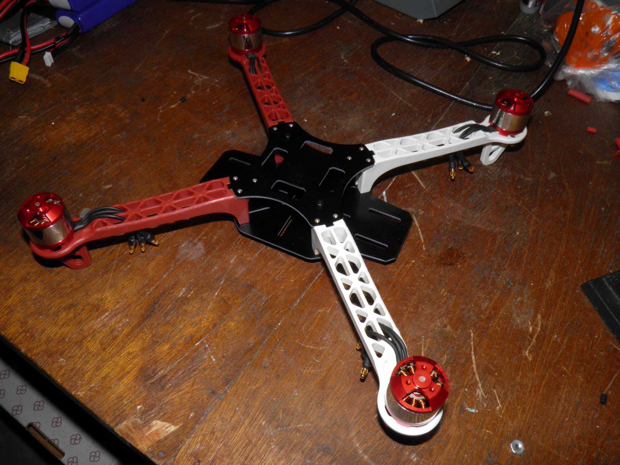
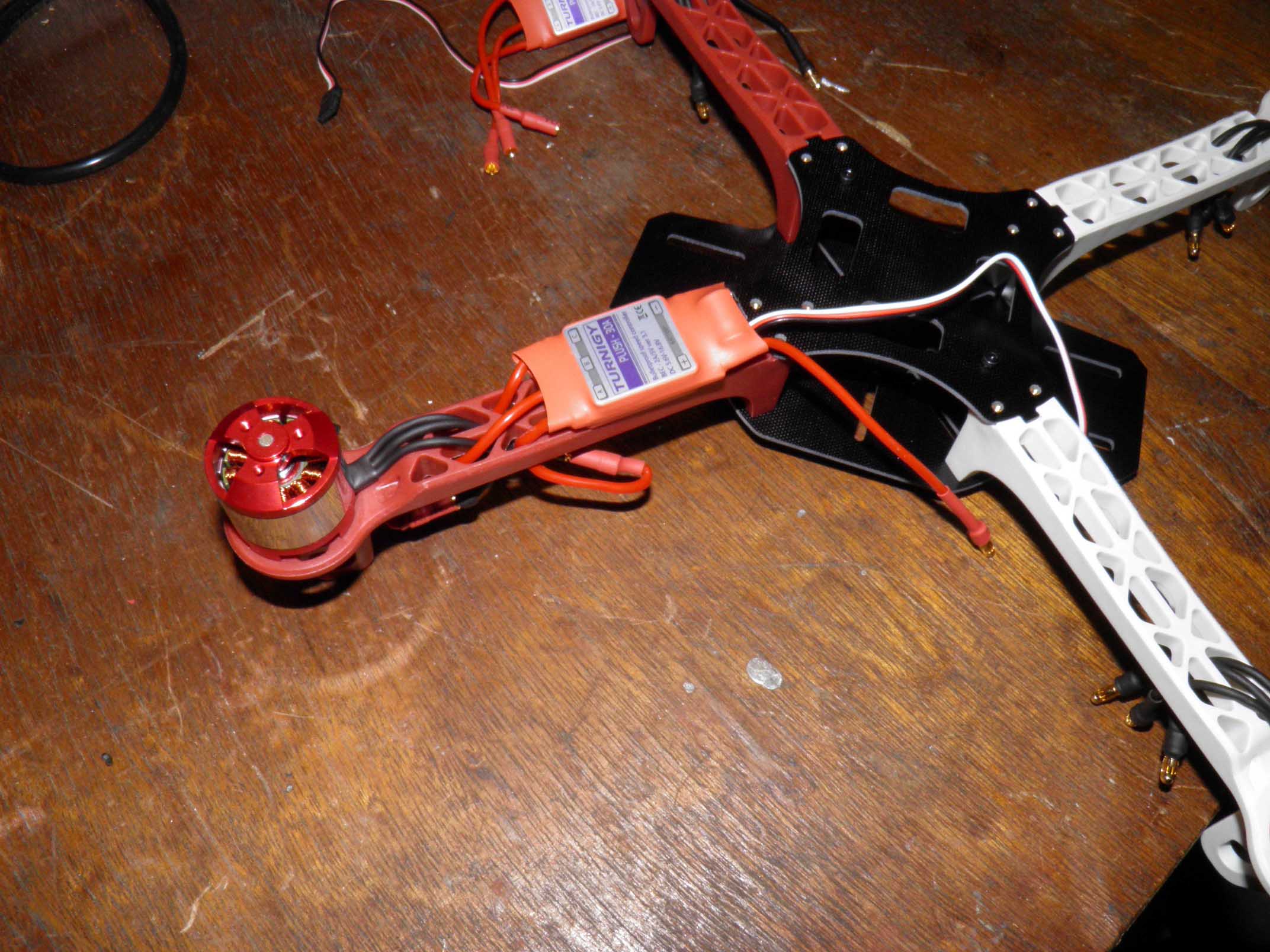
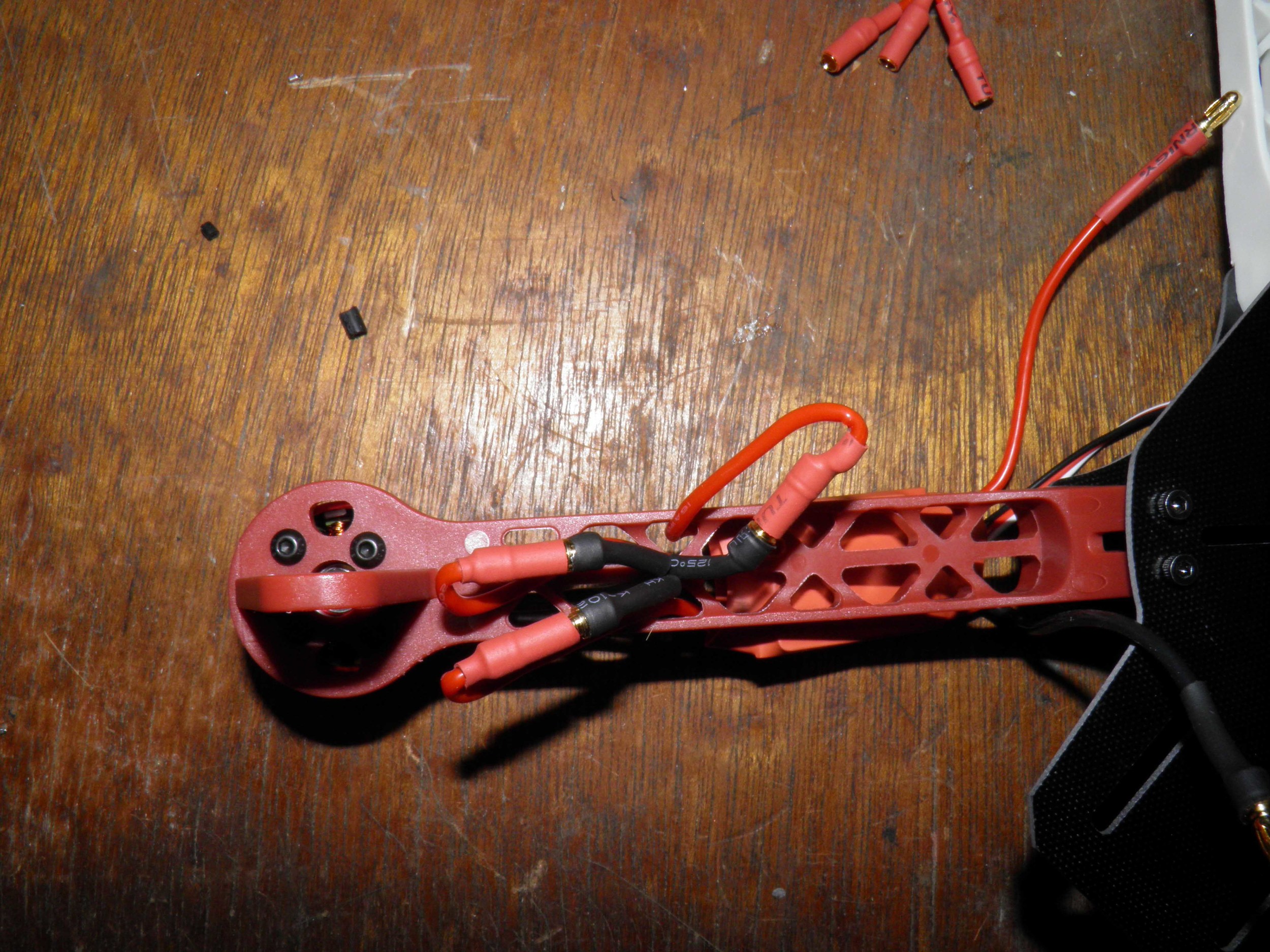
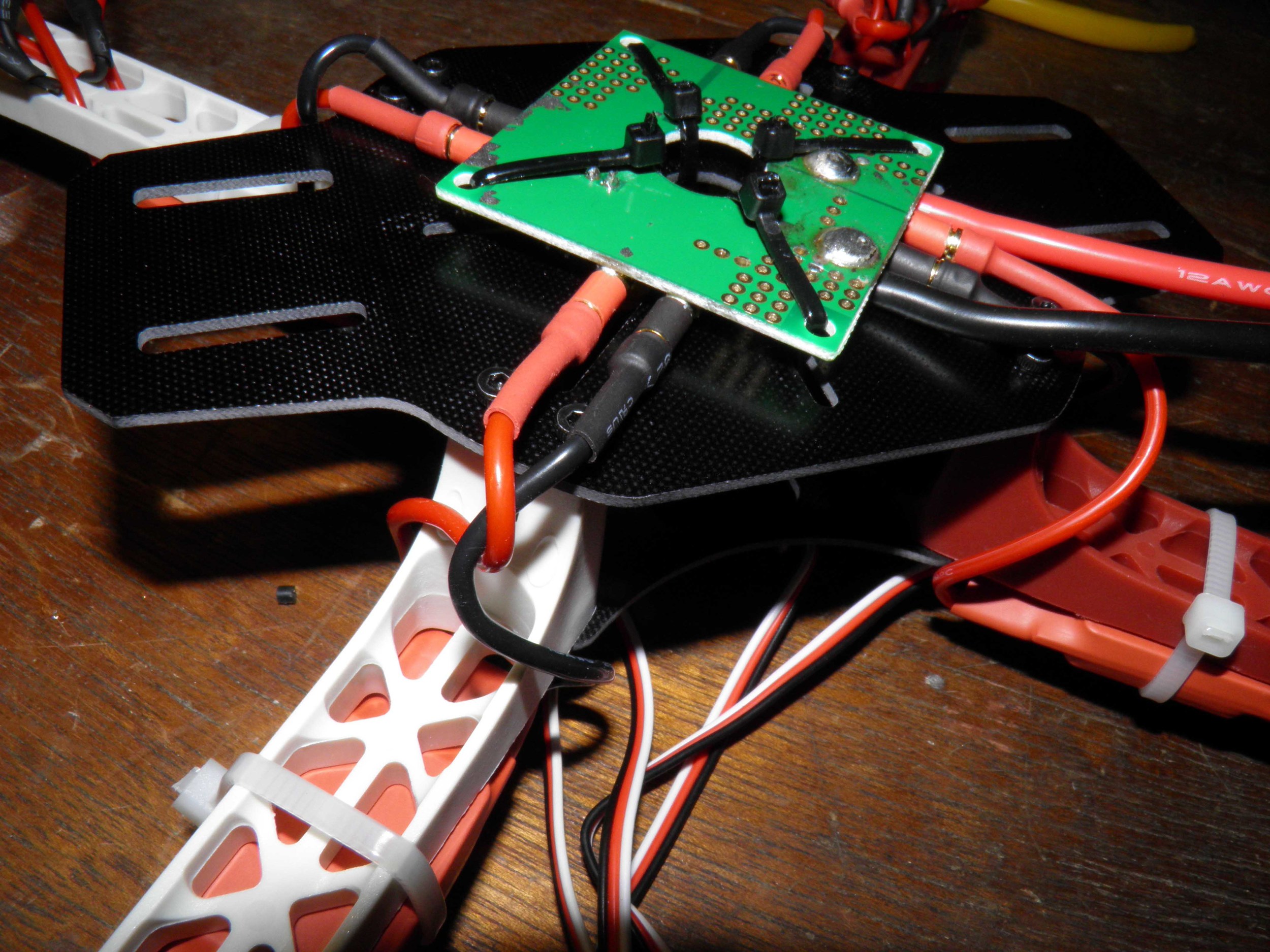
Next the frame is assembled and the mounting positions of the motors, speed controllers, PDB, and battery can be decided upon. The PDB fits nicely on the bottom of the frame with a few zip ties. When the motors are mounted, the wires can be fed through the arms. The speed controllers can be zip tied to the middle of the arms and the leads can be fed through the arms just like the motor's. Connect all the wires up and make sure they will be out of the way of the propellers.