550 Watt PSU to 12 Volt R/C Charger Power Supply
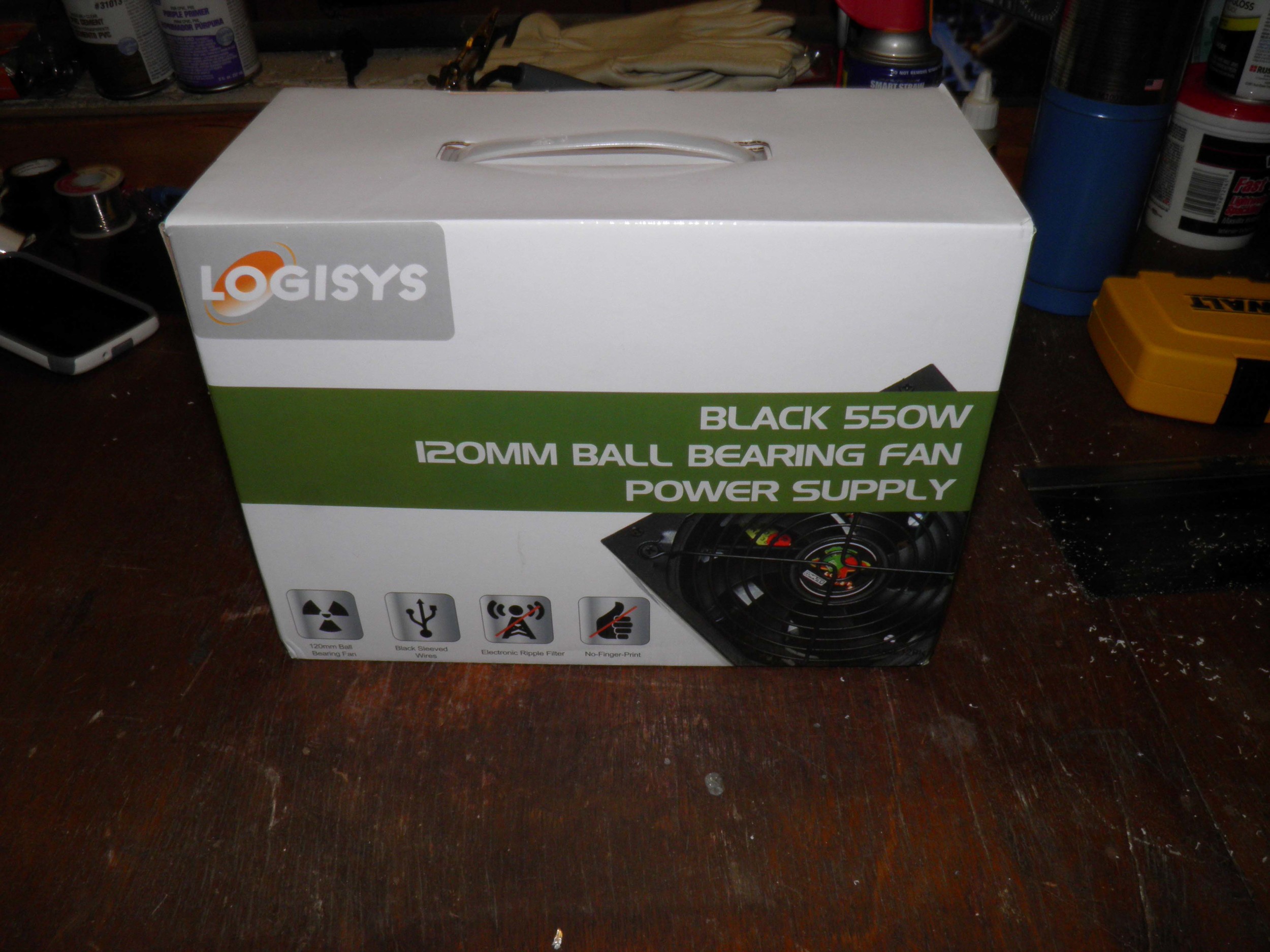
/Last week I decided to take the plunge into R/C quadcopters. With the help of a friend, I composed a fairly large list of parts to order from hobby stores. One of the initial components of R/C is power. How will it be supplied to your R/C craft? What types of batteries will you use? How are you going to charge these batteries? Instead of trying to get into R/C on a budget, I decided to spend a bit more than I wanted so I wouldn't have to upgrade to new and higher quality equipment later on. In doing so, I purchased a Turnigy Accucel-8 150 Watt 7 Amp Balancer/Charger. This specific charger needs to be supplied with 12 volts and it will do the rest; balancing and discharging the batteries to keep them in perfect condition. There are 12 volt power supplies available but I decided to go the DIY route, save a little money, and have a fun afternoon project. I purchased this 550 Watt computer PSU off amazon for about $24.
WARNING: These power supplies contain large capacitors capable of delivering a hefty shock. Be sure to fully discharge your PSU before starting any work if you have plugged it in recently.
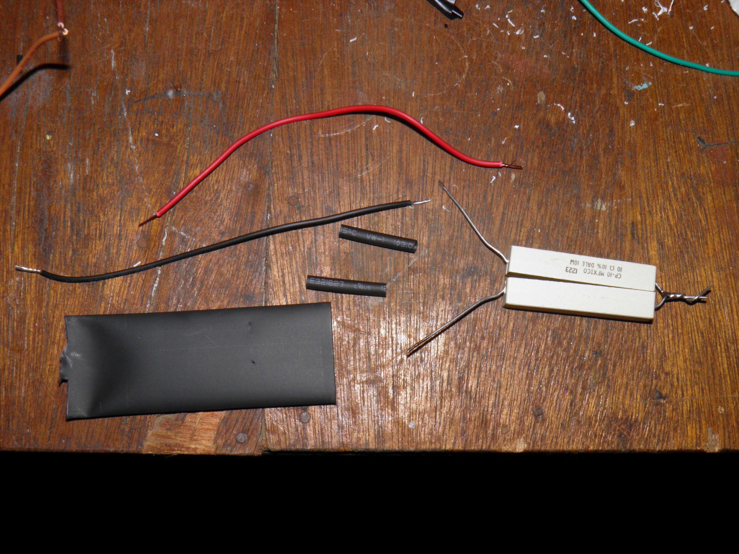
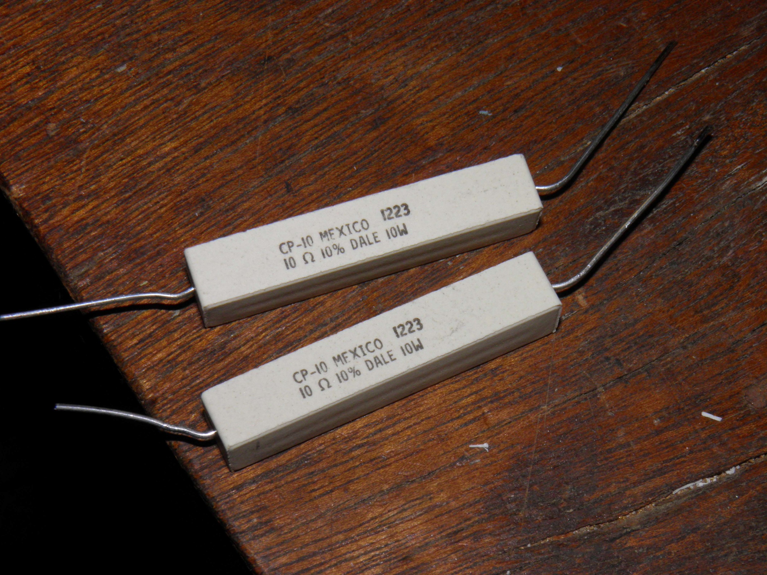
I also needed a "dummy load" of a 20 Ohm 10 Watt resistor to keep the power supply from faulting and turning off immediately. I only had 10 Ohm 10 Watt resistors available so I just wired two of those up in series. A few other miscellaneous parts were heat shrink tubing, zip ties, and a soldering iron/solder.
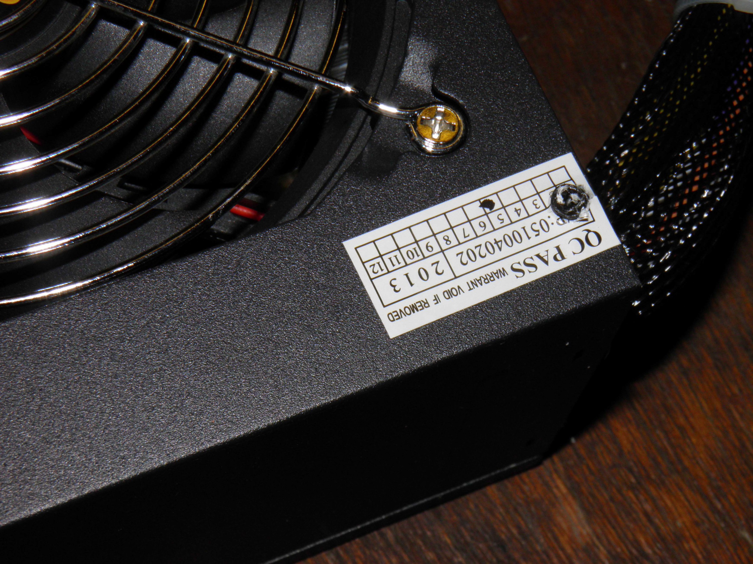
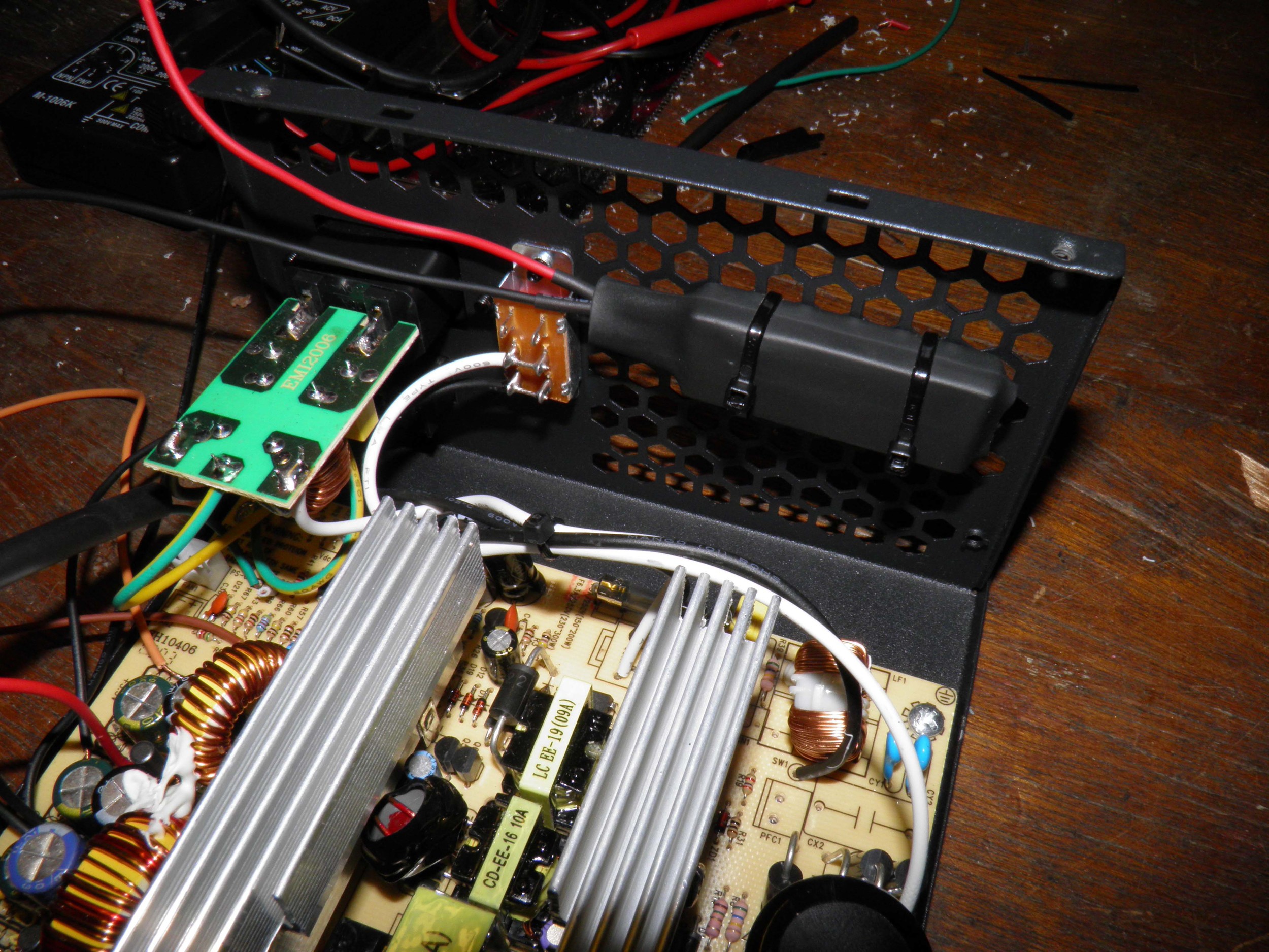
The first step was to open up the PSU case to access the main circuit board. There are four screws on the top, one hidden under the QC sticker. I unplugged the fan from the board and set that aside. I clipped the zipties and popped out the plastic organizer circle.
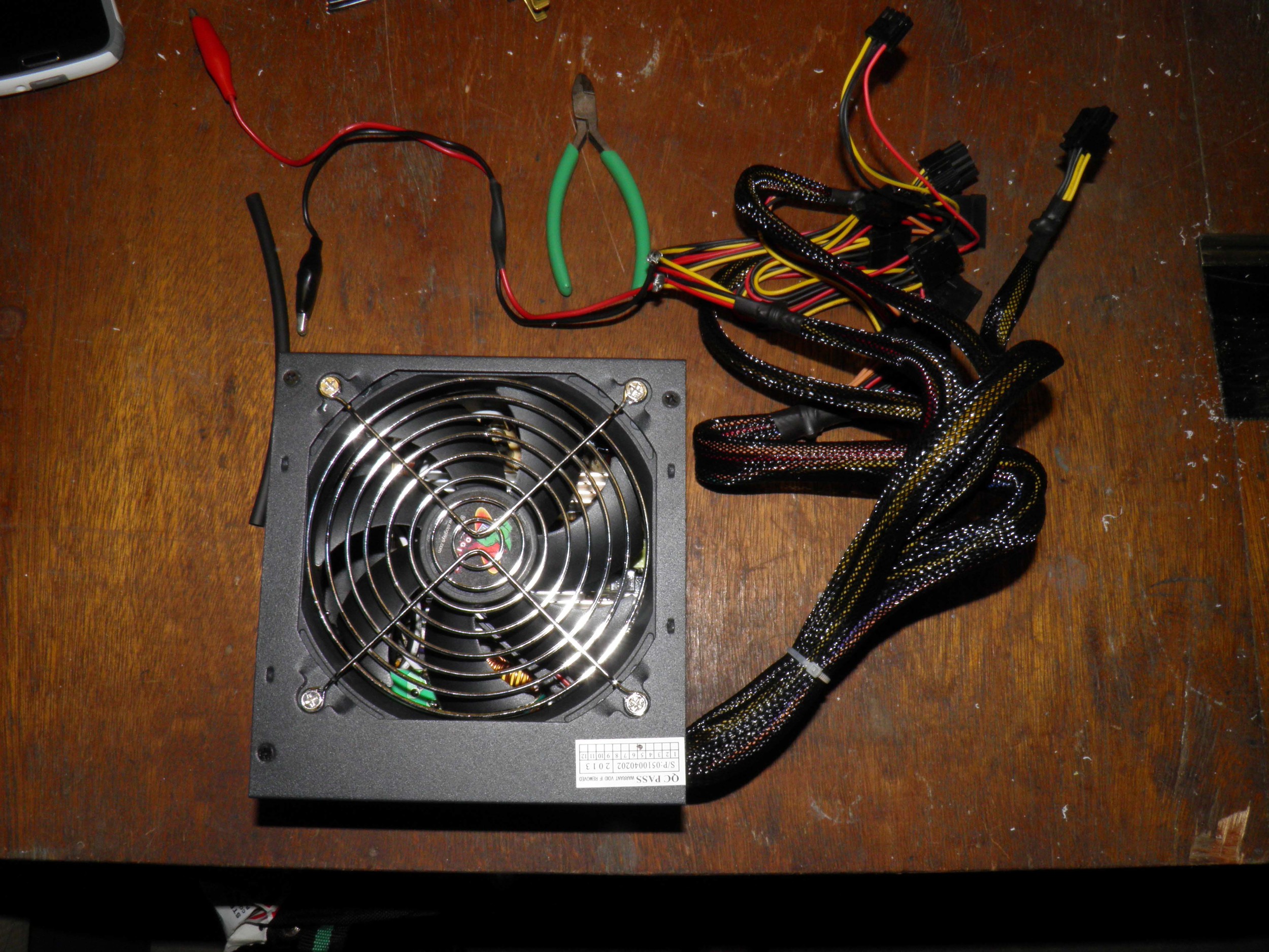
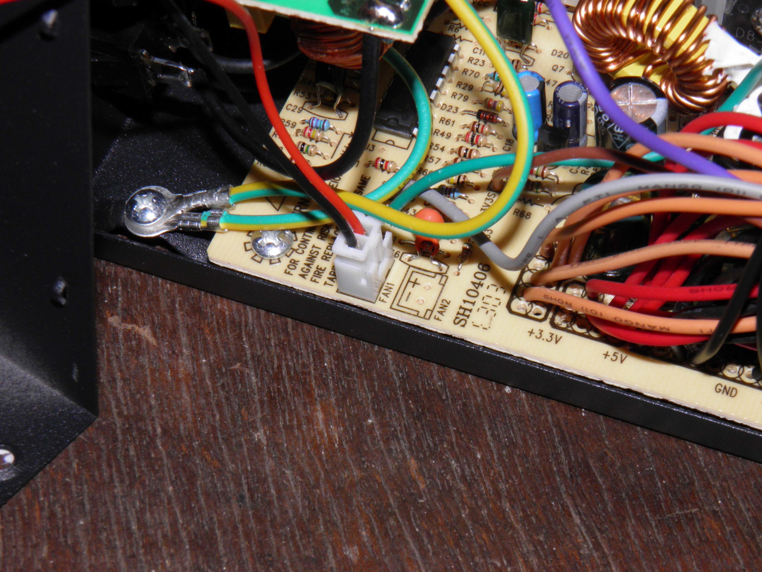

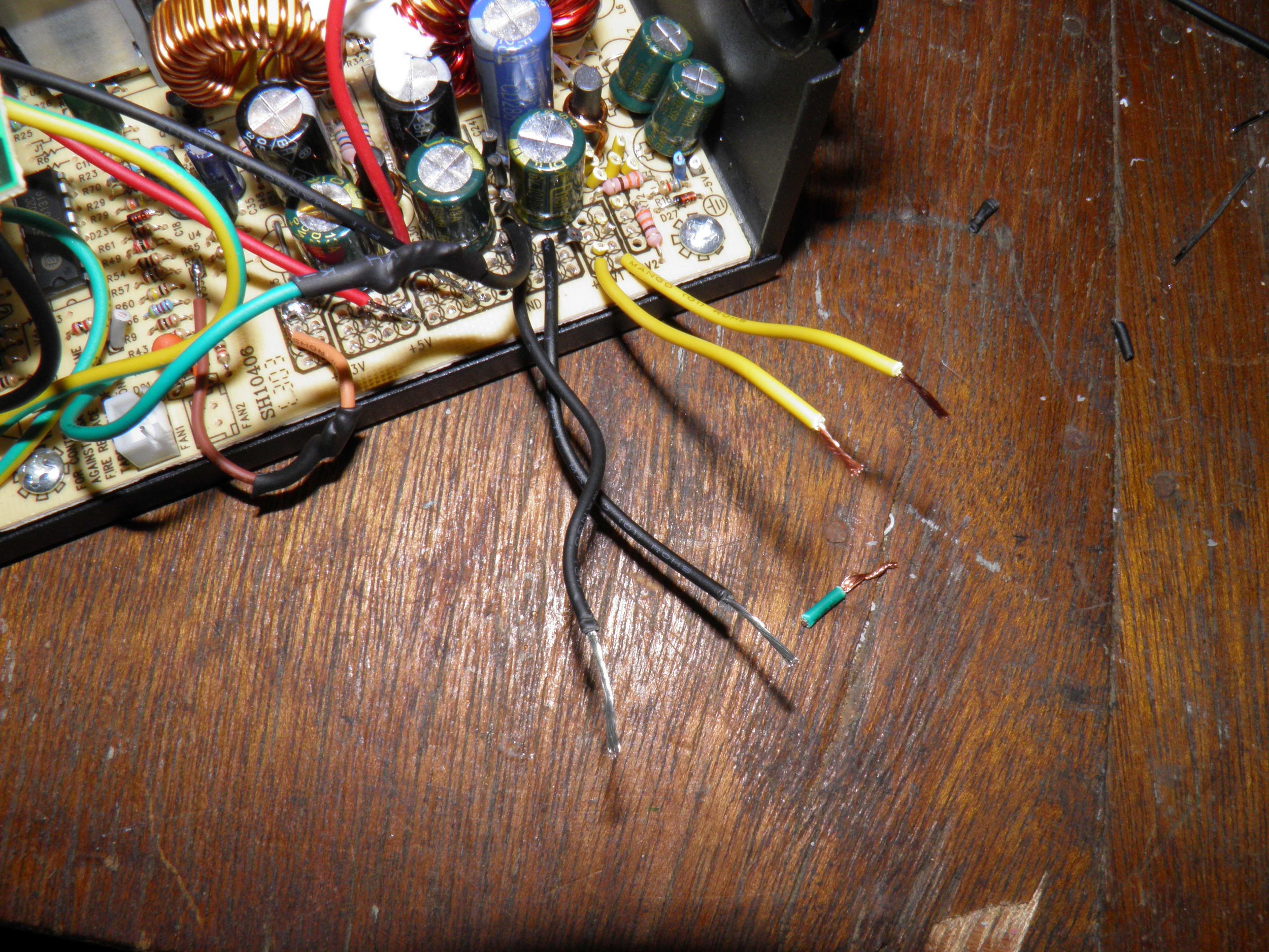
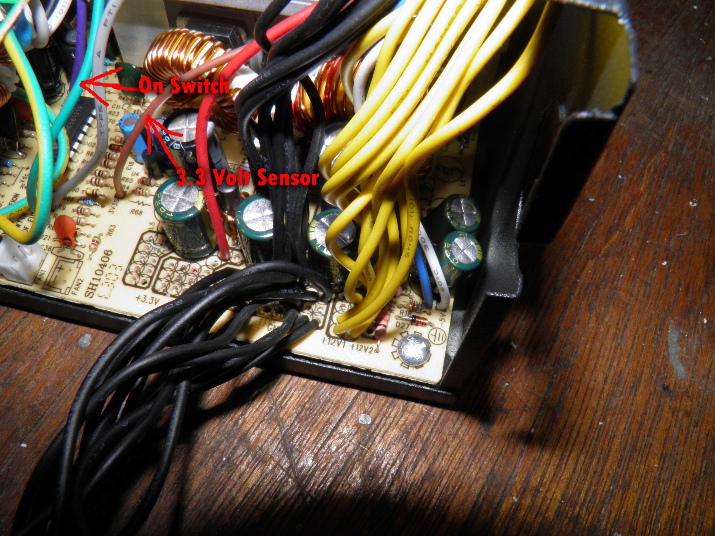
There are a lot of extra wires in the PSU that we no longer need.
You can cut away all but one of the orange +3.3 volt wires, all but one of the red +5 volt wires, all but four of the black ground wires, and all but two of the yellow +12 volt wires. You'll also need to keep the brown and green wires that are to the left of
the ground/various voltages. These are needed to trick the PSU into
powering on. The brown +3.3 volt sensing wire needs to be attached to the orange +3.3 volt wire and the green power on switch will need to be grounded. I soldered these connections and put some heat shrink on them.
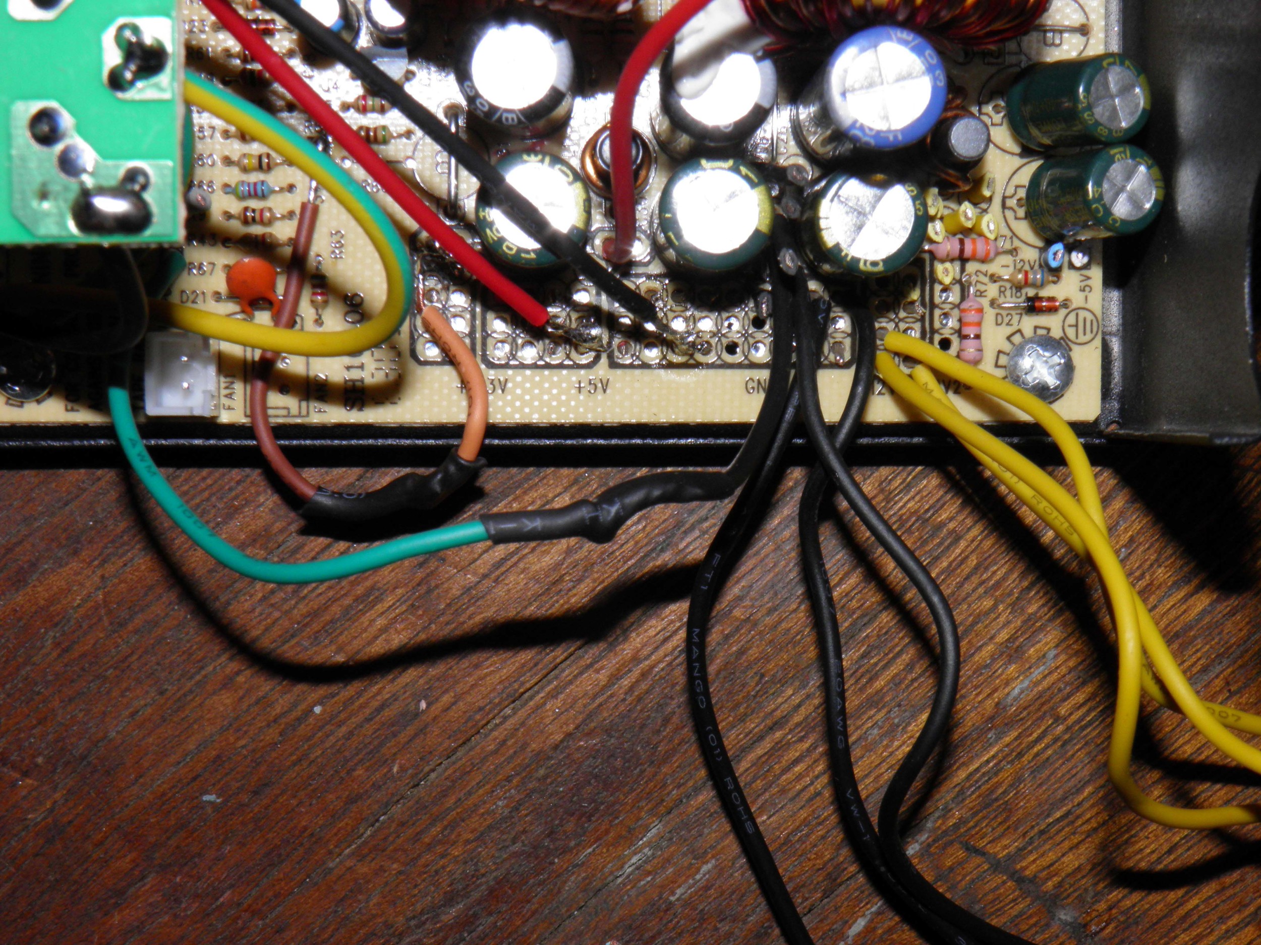
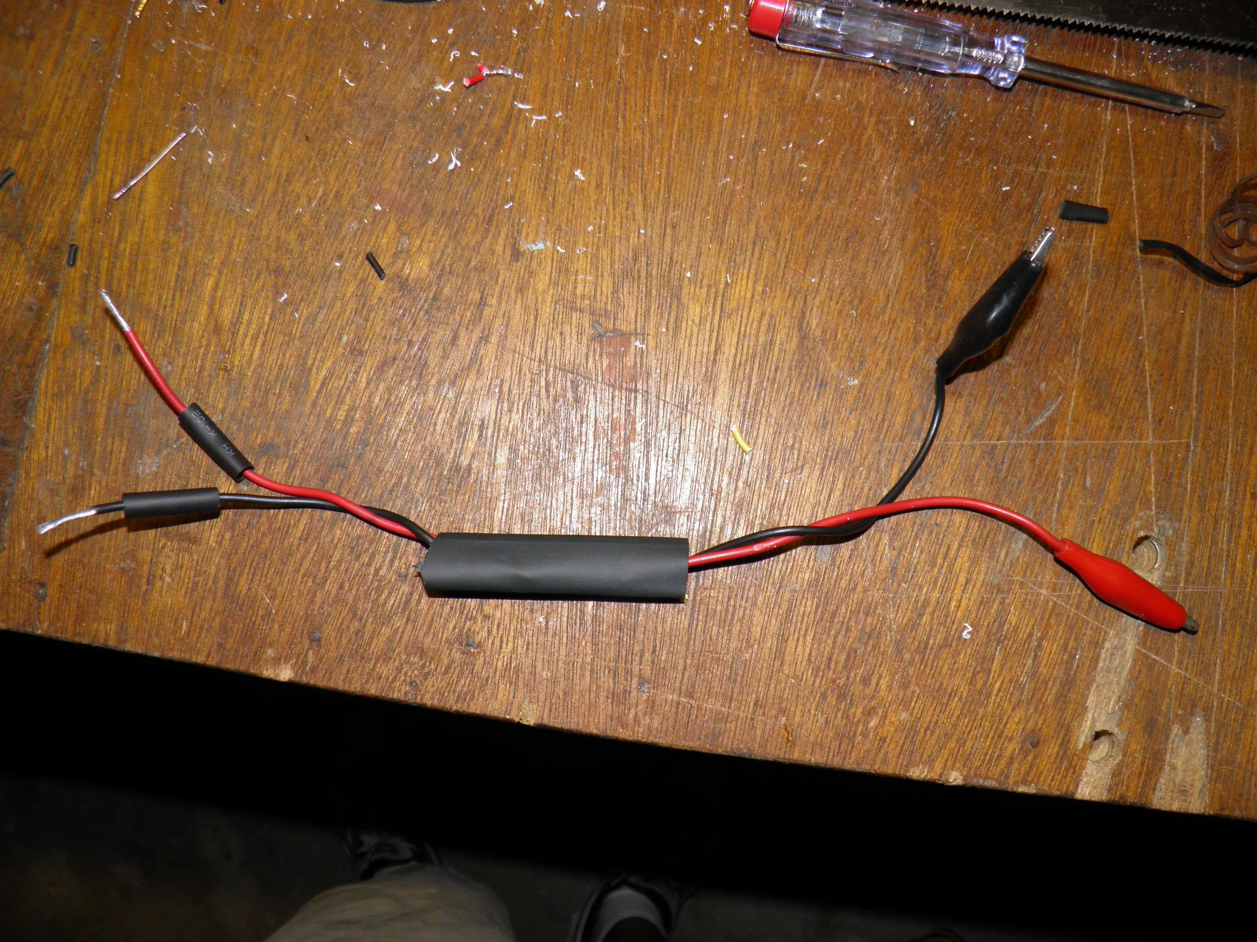
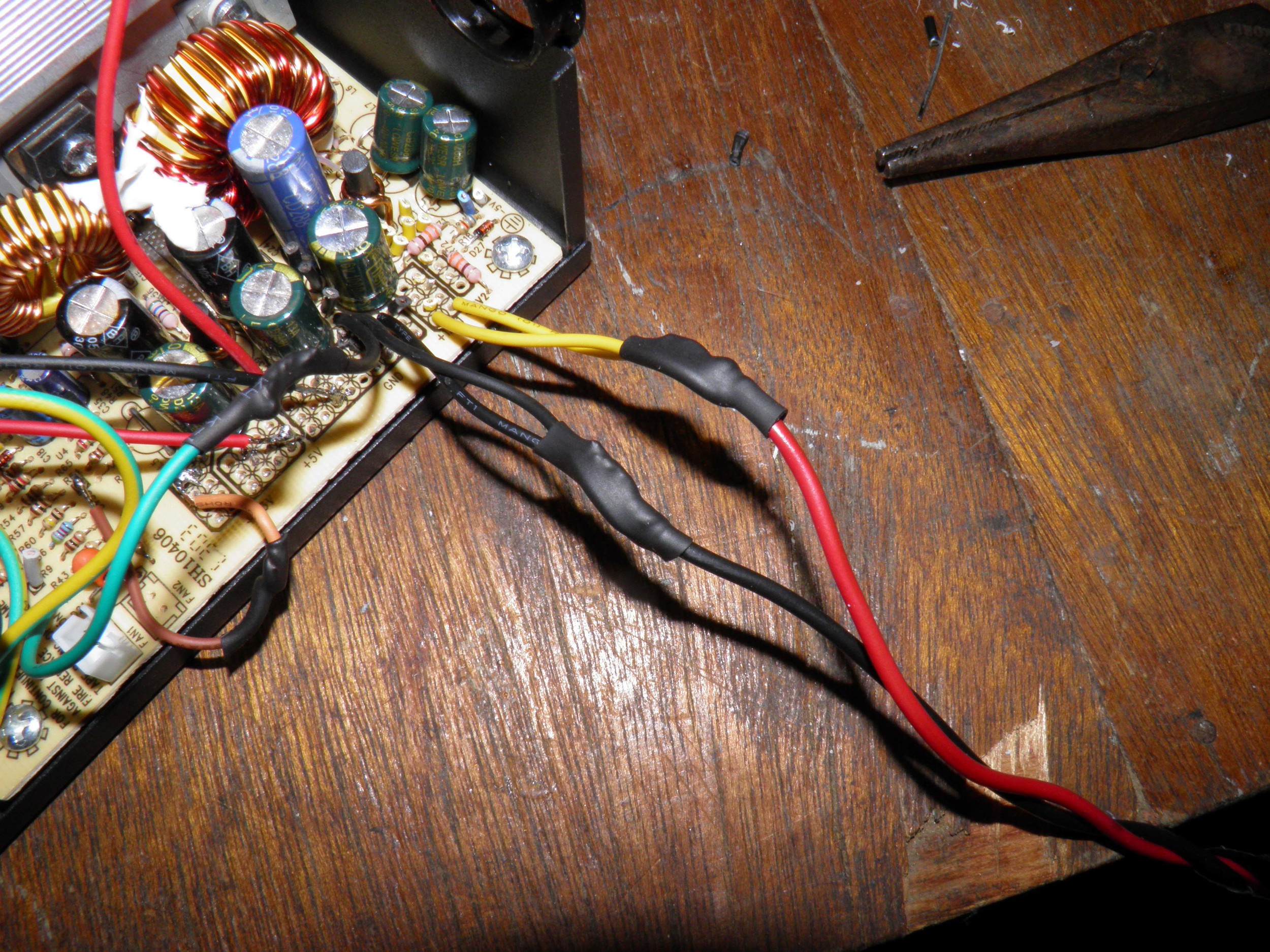
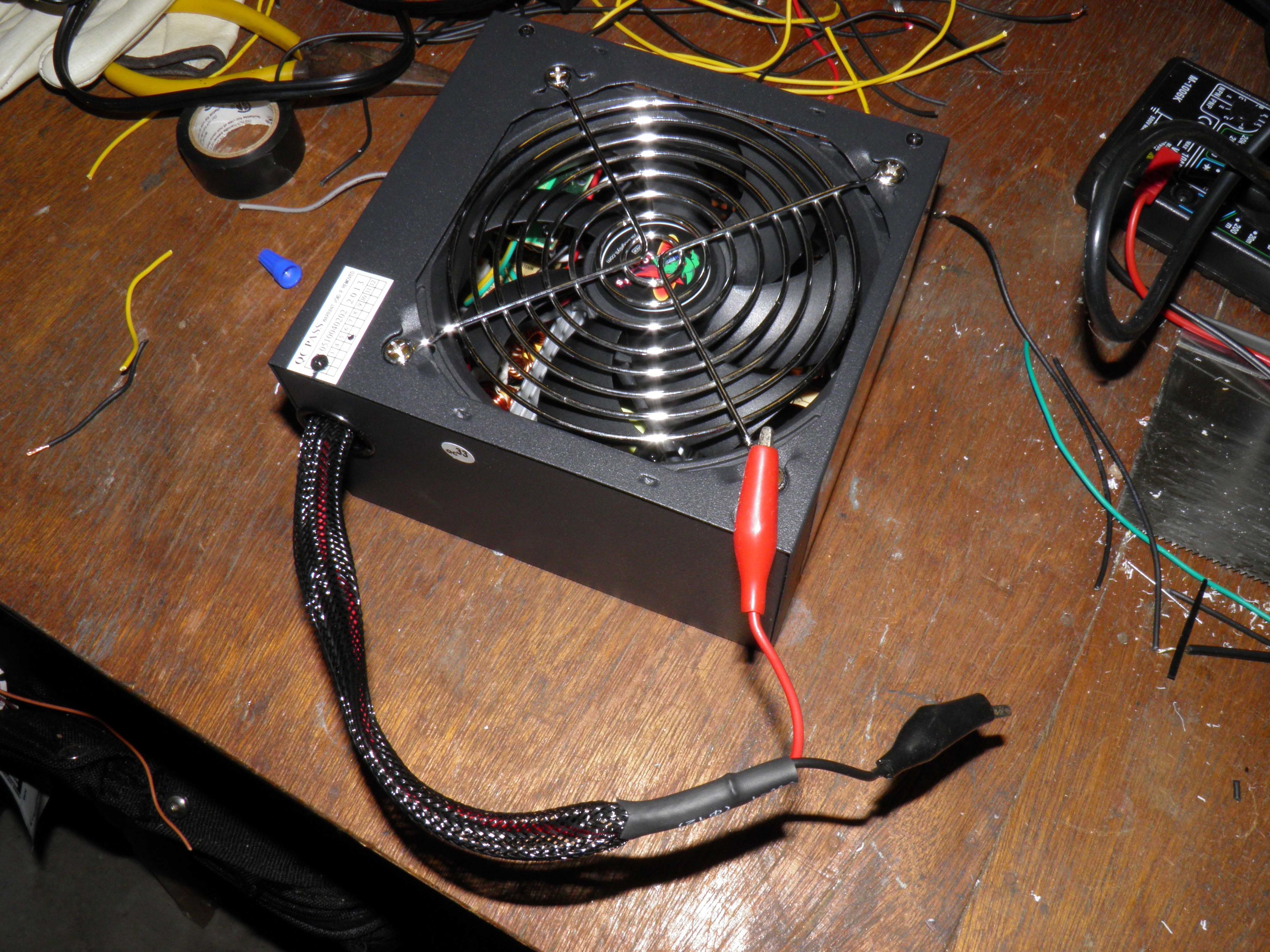
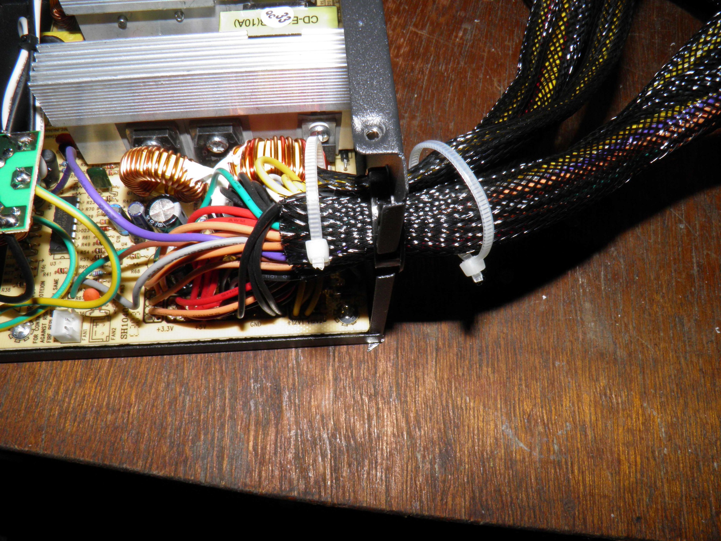
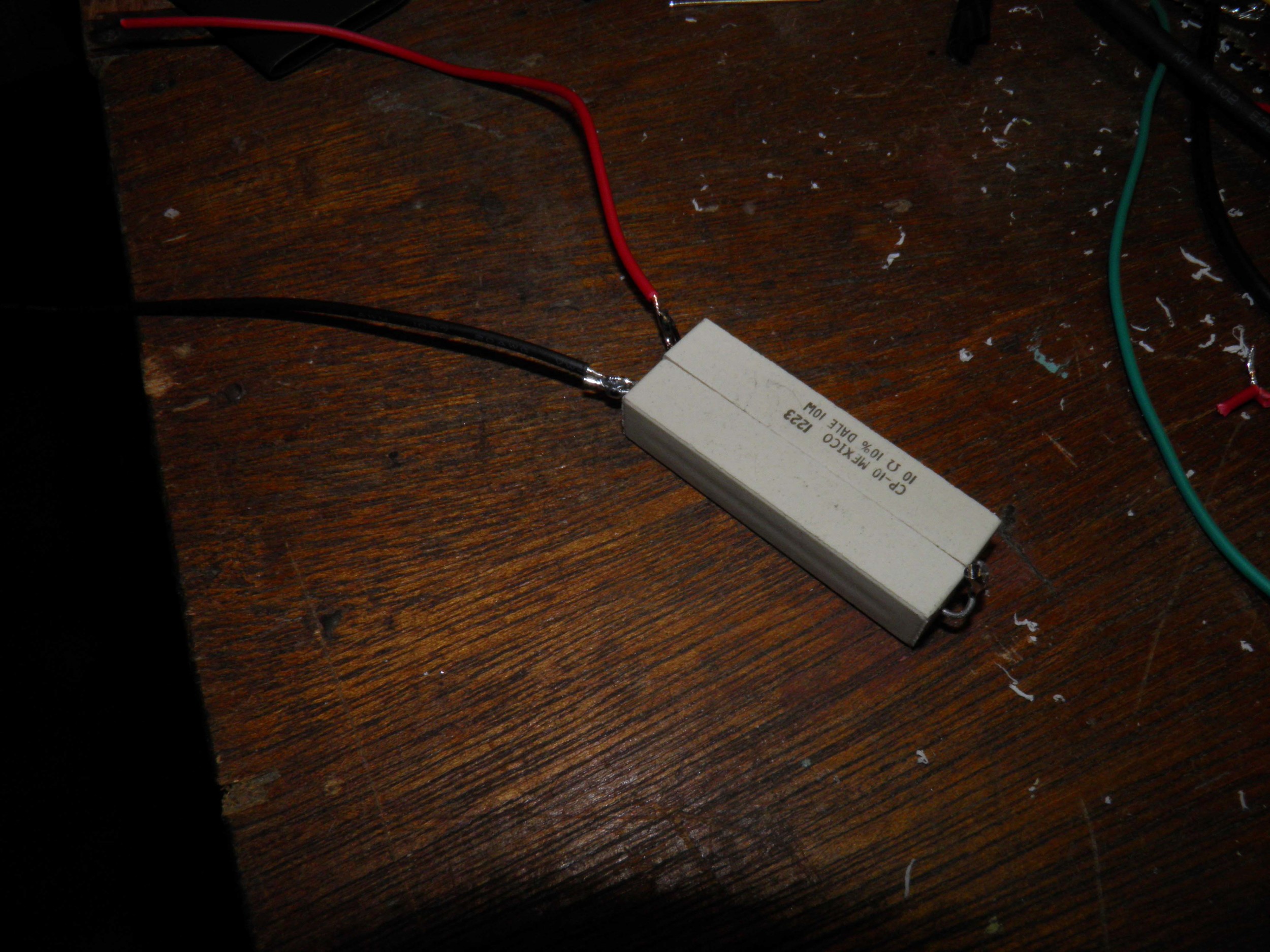
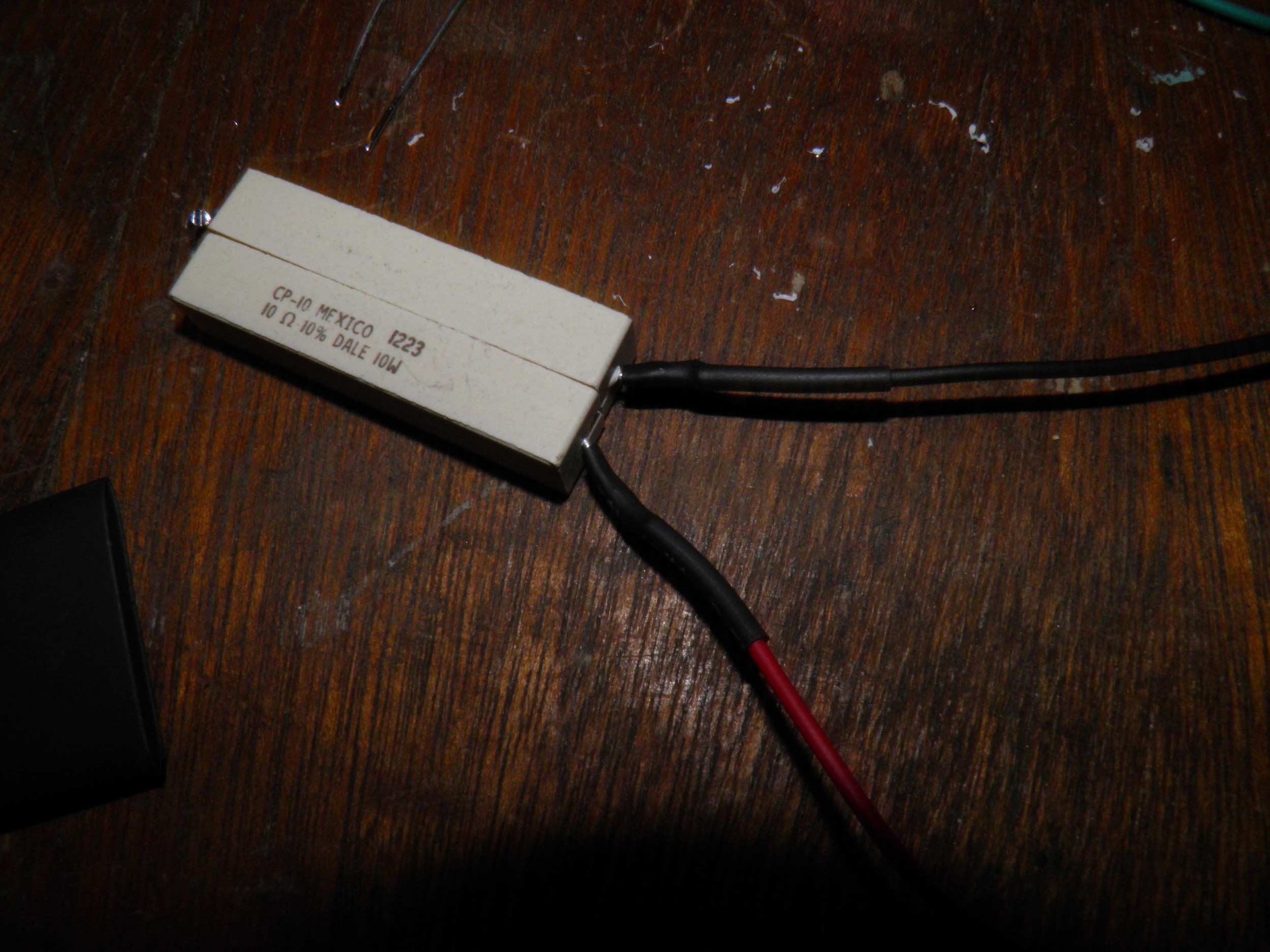
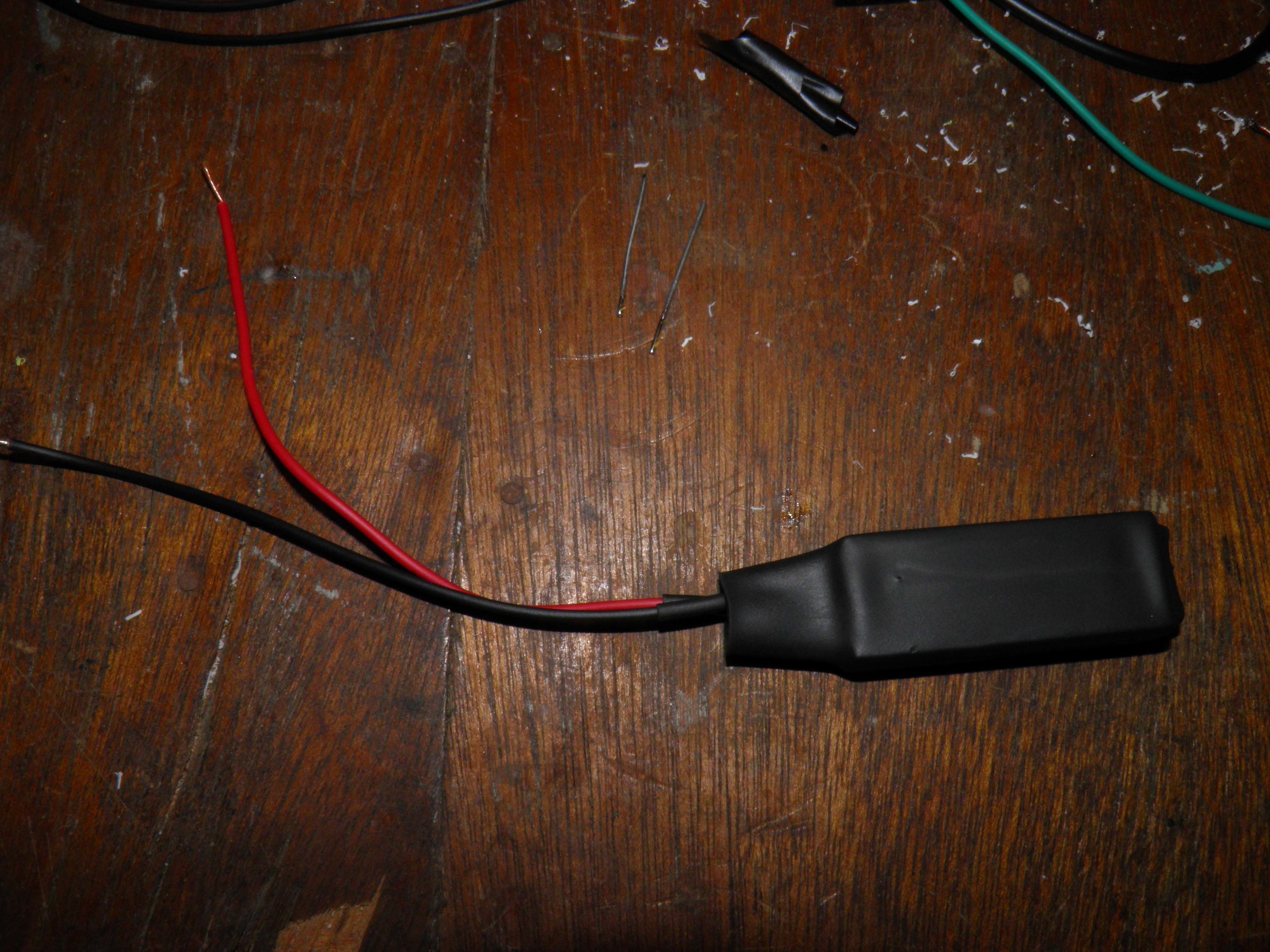
Next I prepared the resistors. This was the first time using my new heat shrink tubing and I may have went a little overboard... I paired the two resistors together, twisted one pair of leads, and soldered them together. I took two wires and soldered them close to the base of the resistor and put heat shrink on the solder connections. I then put heat shrink on the entire resistors to protect it from any possible shorts. To fasten it to the PSU, I ziptied the resistors to the exhaust port. This provides a convenient mounting location and will also help any heat generated by the resistors will be dissipated efficiently. The red wire is soldered to +5 Volts and the black wire is soldered to ground.


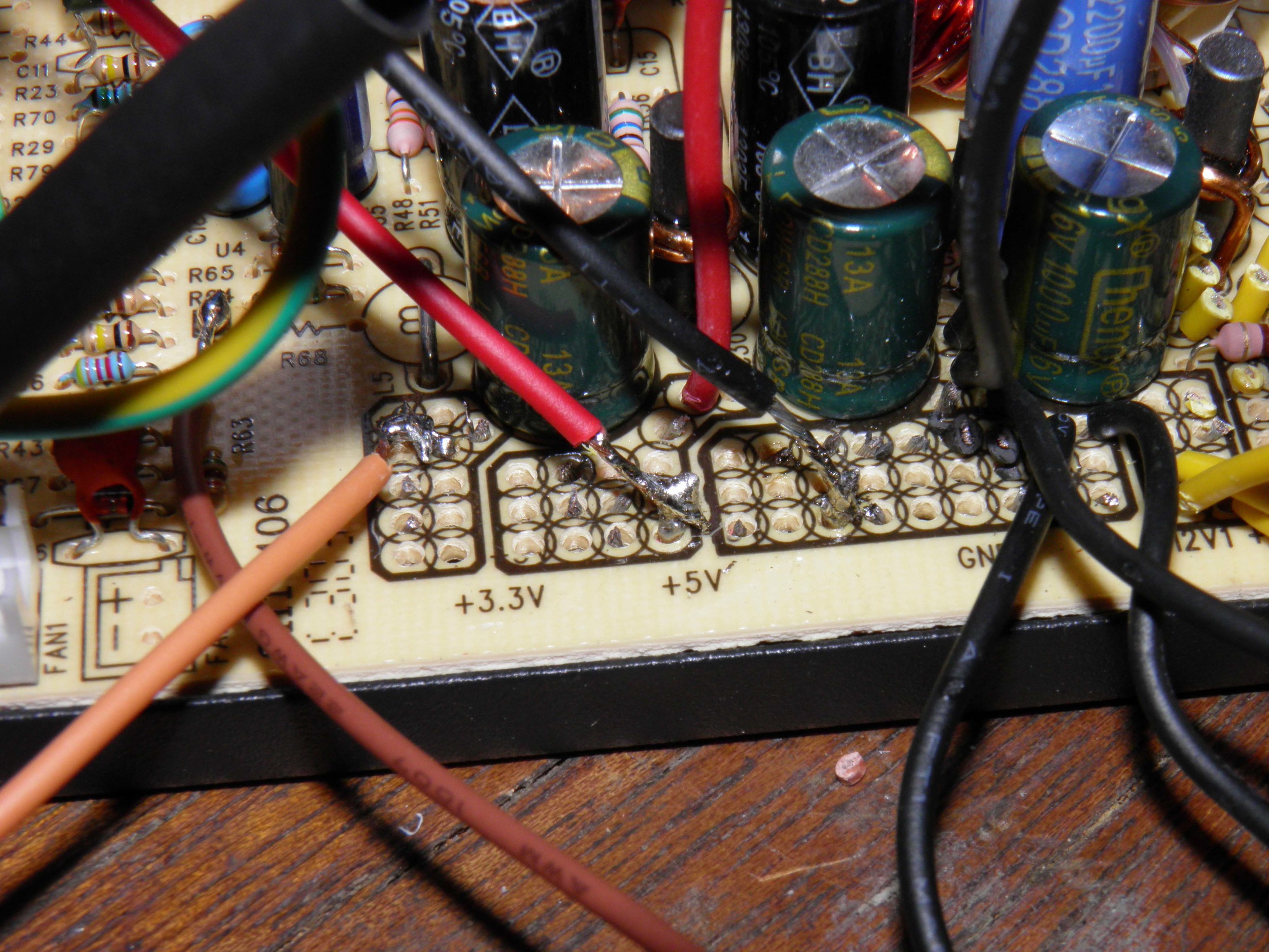
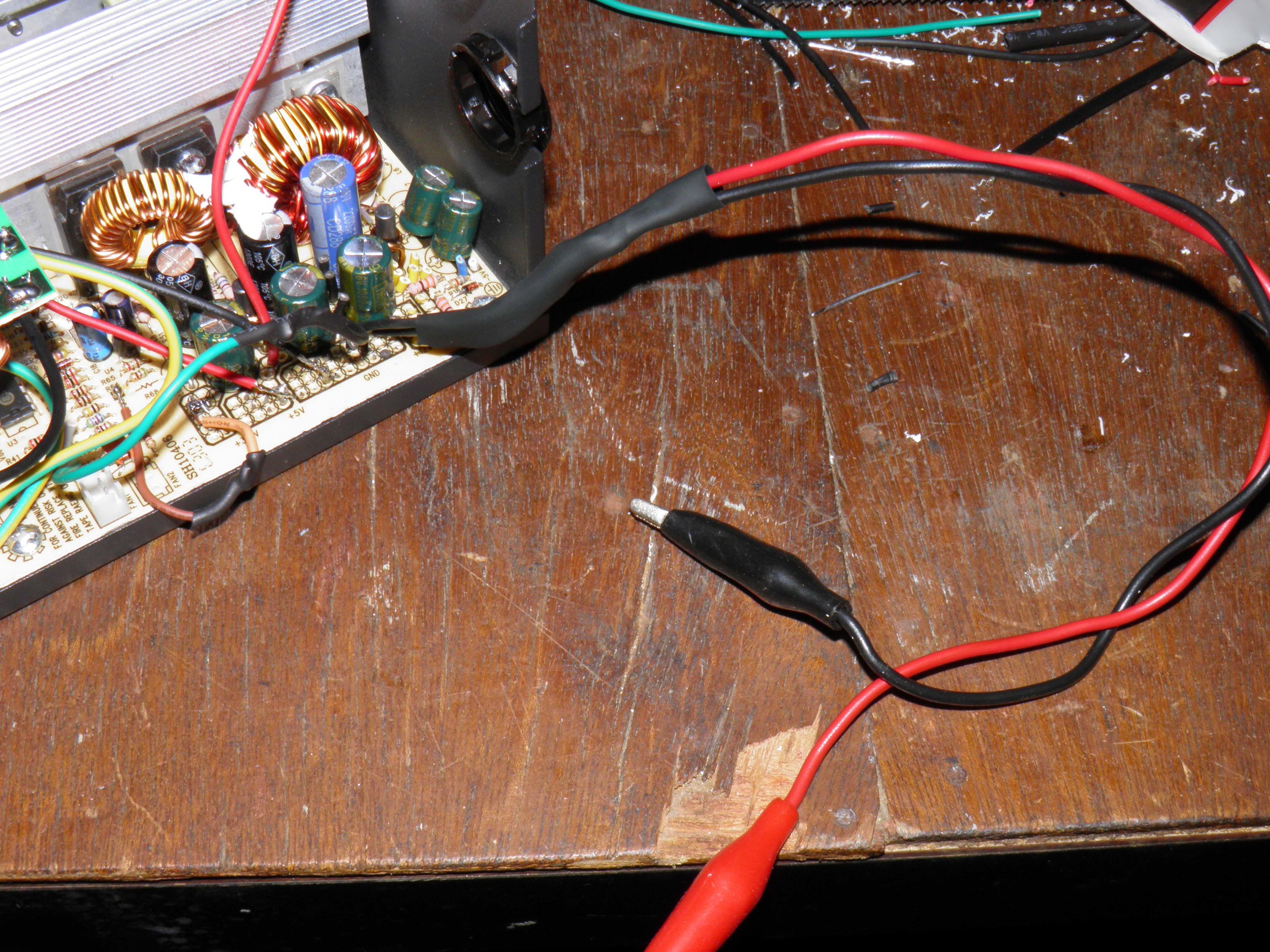
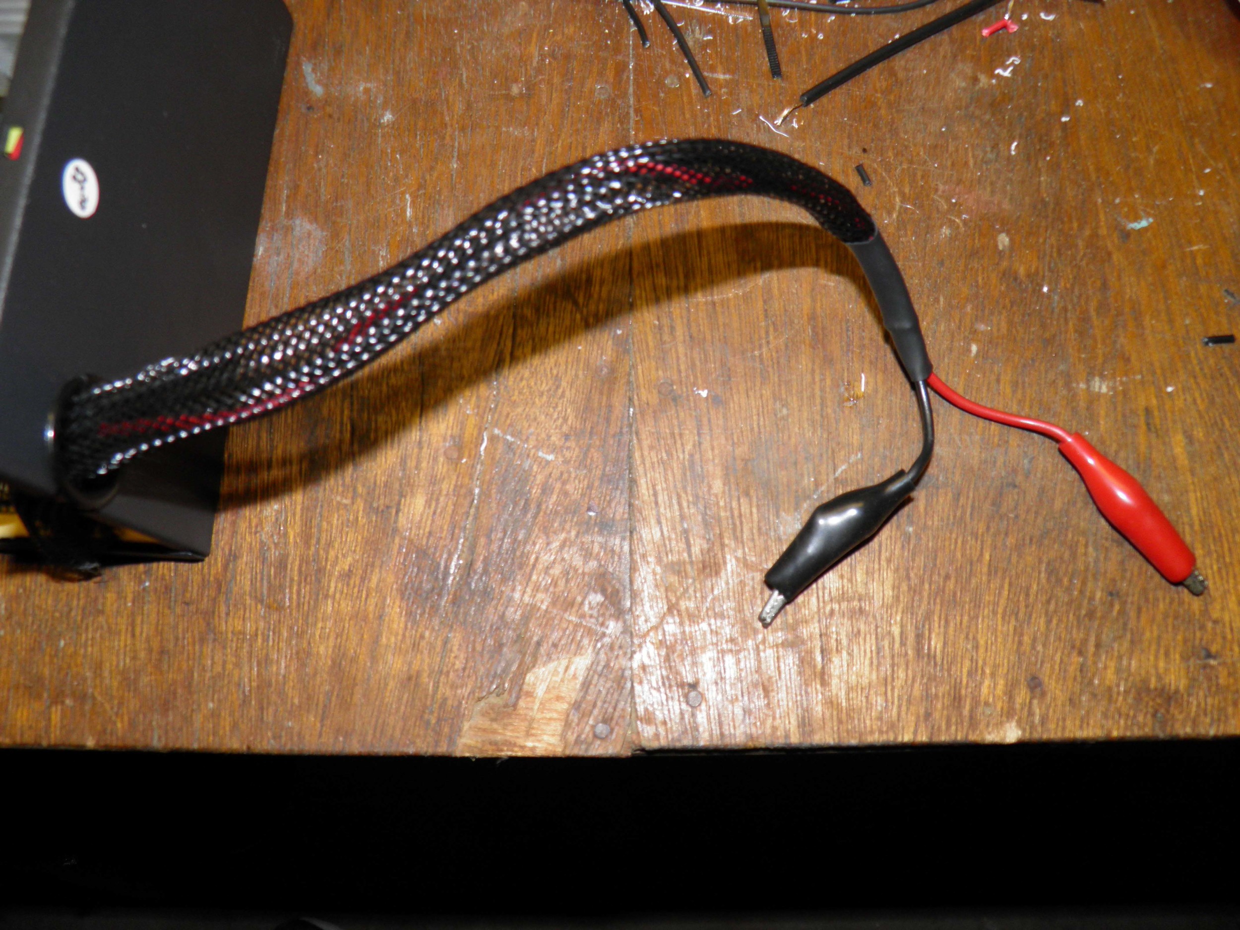
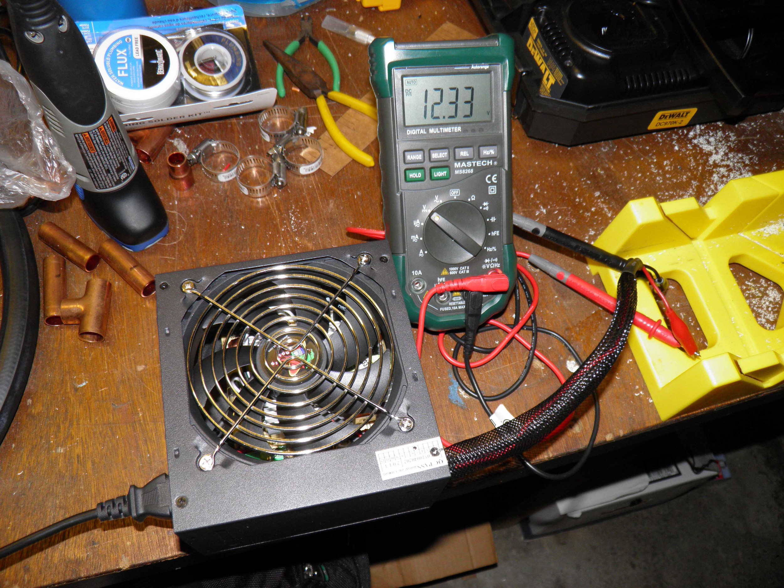
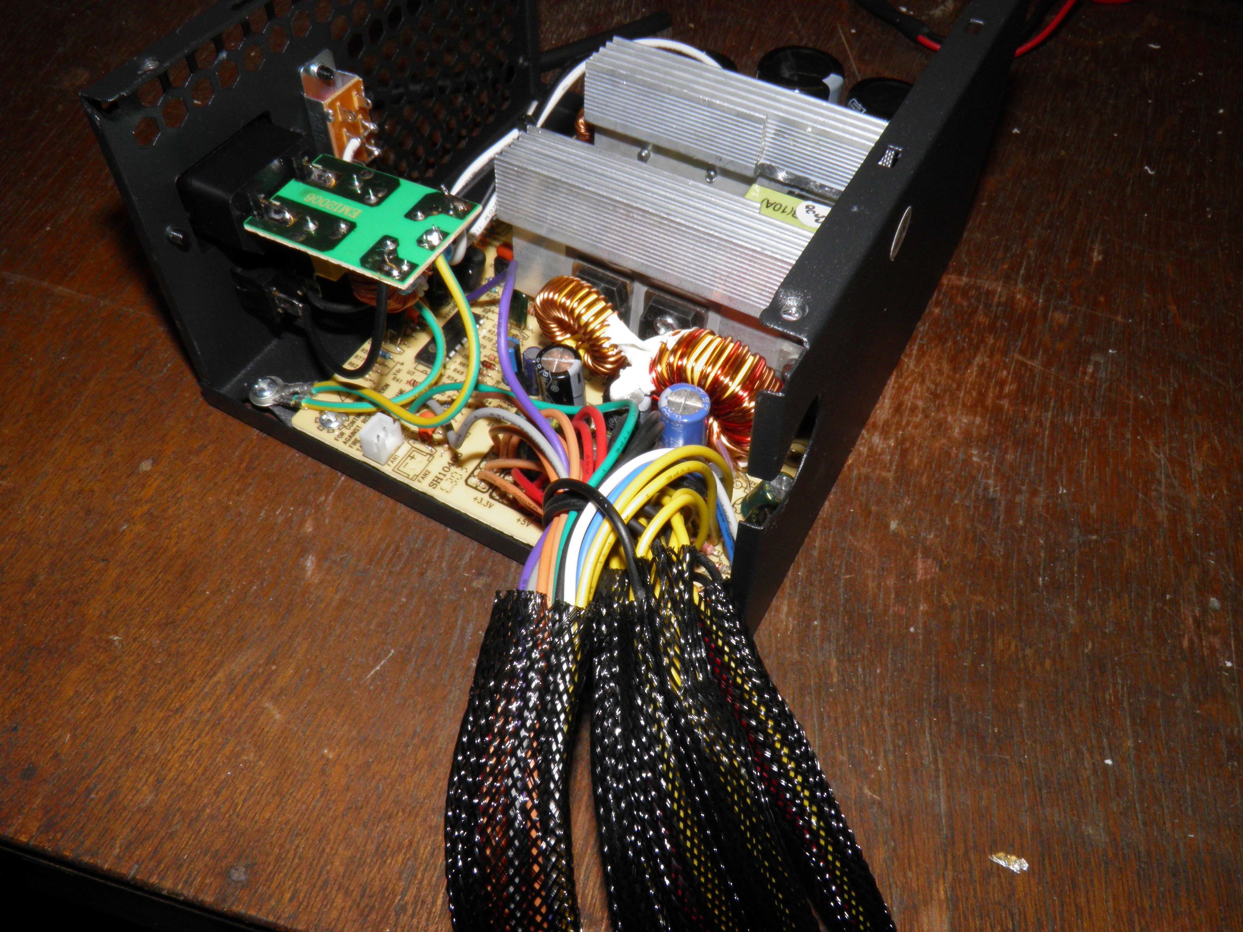
To finish the power supply up, we just need to solder on some connectors. I had a nice set of alligator clips laying around so I used those. I twisted the yellow +12 volt wires to the red and the ground wires to the black alligator clip. I soldered and put some heat shrink on them. The wires within the PSU were labeled 20 AWG guage wire meaning they are capable of operating at 11 Amps. The charger that I purchased can only use 7 Amps max and I will be charging my batteries around 3.6 Amps, so these wires are sufficient for this appliction. I used some of the mesh wire organizer and the plastic cable ring left over from the tear down to make it look neat and organized. I finished up by adding some heat shrink, plugging the fan back in, and putting the cover back on. At this point you will have a 20 Ohm 10 Watt resistor connected from +5 volts to ground acting as the dummy load, the power on switch grounded to turn the PSU on, the brown +3.3 volt sensor wire connected to an orange +3.3 volt wire to keep the PSU on, and the yellow +12 volt wires connected to the alligator clips for use with your R/C battery charger. Without a load on the PSU, it's outputting around 12.3 volts DC.